
Site-Specific Planning
Views and pathways are selected around the technical decision and the actual commercial property, not a generic device count.
COMMERCIAL SECURITY AND LOW-VOLTAGE RESOURCE
A complete fiber system defines more than the cable. It specifies link distance, bandwidth, single-mode or multimode context, strand count, indoor or outdoor construction, pathway, bend and pulling limits, splice or connectorized termination, enclosures, optics responsibility, testing, labels, spare capacity, and service access.
This guide explains the technical variables, tradeoffs, failure modes, and contractor questions that matter for fiber optic installation systems. Use it to prepare a scope, then verify property-specific conditions before implementation.
PROJECT DETAILS
Views and pathways are selected around the technical decision and the actual commercial property, not a generic device count.
Cameras, recording, cabling, network, access and related dependencies are reviewed as one operating system.
Work zones and cutovers are organized around approved access, occupancy and network windows.
Labels, device schedules, test results, user ownership and exceptions support ongoing service.
Commercial low-voltage work is provided under FL License #EC13016138.
SERVICE OVERVIEW
A complete fiber system defines more than the cable. It specifies link distance, bandwidth, single-mode or multimode context, strand count, indoor or outdoor construction, pathway, bend and pulling limits, splice or connectorized termination, enclosures, optics responsibility, testing, labels, spare capacity, and service access.
The decision is complete only when the required outcome, field conditions, infrastructure, operating owner, limitations, and acceptance method agree with one another.
CORE CAPABILITIES
Selection depends on link distance, installed optics, application, existing standards, future capacity, and lifecycle strategy.
Count active transmit and receive needs, redundancy, growth, spare strands, and any diverse-route strategy.
Conduit condition, fill, pull points, tensile load, bend radius, crush risk, building entry, and environmental rating protect the cable during and after installation.
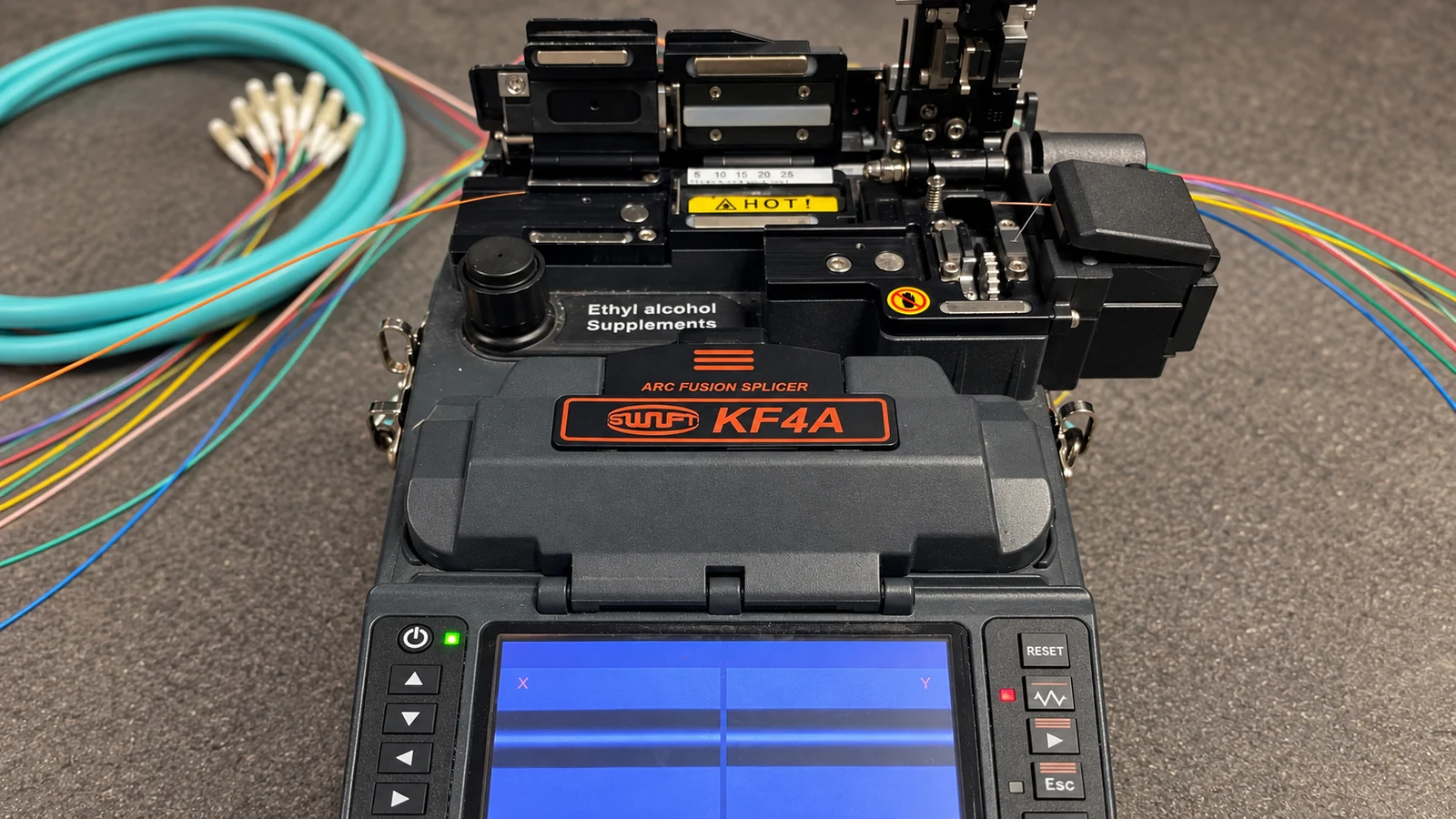
Fusion splicing can support pigtails and repairable enclosure design; preterminated assemblies can reduce field termination but require pathway and length control.
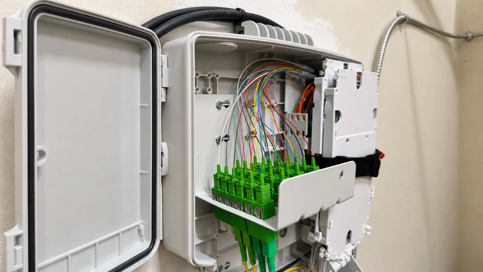
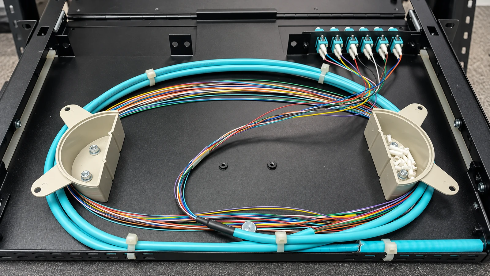
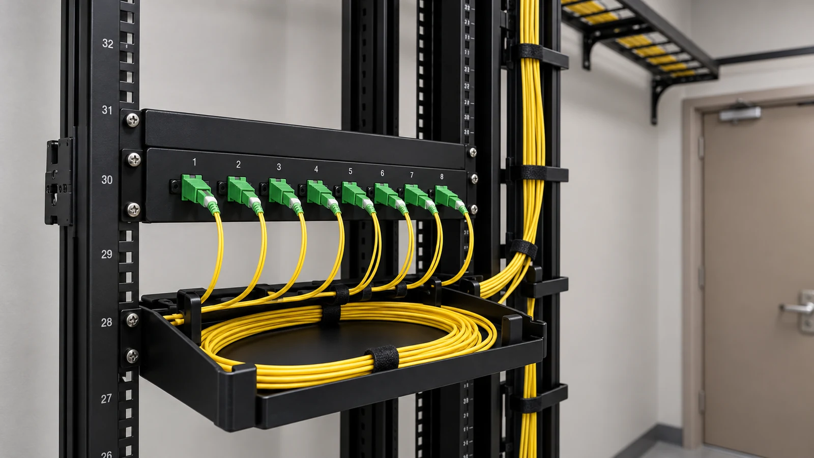
Rack and wall enclosures should protect bend radius, adapters, splice trays, slack, and connectors while keeping both ends consistently labeled and accessible.
Continuity is not enough.
ORLANDO SERVICE CONTEXT
Western Greater Orlando properties range from visitor-facing hospitality and retail to offices, healthcare, warehouses, managed communities and active construction. The correct answer changes with occupancy, work windows, weather exposure, network ownership and the physical distances at the actual site.
Orlando fiber routes may cross hot warehouses, wet exterior pathways, active hospitality properties, or separate buildings exposed to lightning and construction. Route protection, enclosure location, building entry, spare strands, and test records should be planned before the pull.
TECHNICAL PLANNING
Single-mode and multimode context
Selection depends on link distance, installed optics, application, existing standards, future capacity, and lifecycle strategy. Jacket color or a general distance rule is not an adequate design basis.
Strand count and future capacity
Count active transmit and receive needs, redundancy, growth, spare strands, and any diverse-route strategy. Installing too few strands can make a later expansion depend on another cable pull.
Pathway, pulling, and bend control
Conduit condition, fill, pull points, tensile load, bend radius, crush risk, building entry, and environmental rating protect the cable during and after installation.
Splice versus connectorized termination
Fusion splicing can support pigtails and repairable enclosure design; preterminated assemblies can reduce field termination but require pathway and length control. The right choice depends on route and service conditions.
Enclosures, labels, and serviceability
Rack and wall enclosures should protect bend radius, adapters, splice trays, slack, and connectors while keeping both ends consistently labeled and accessible.
Testing and optical budget
Continuity is not enough. Loss testing and, where appropriate, trace testing should match the project’s acceptance method, record both ends, and identify abnormal loss or events.
PROJECT DETAILS
Fiber can cross long or electrically noisy routes, but each building needs protected entry, enclosure space, optics, grounding boundaries, and test records.
Backbone strands, diverse operations, occupied work windows, and separate telecom rooms require a label and activation plan by building.
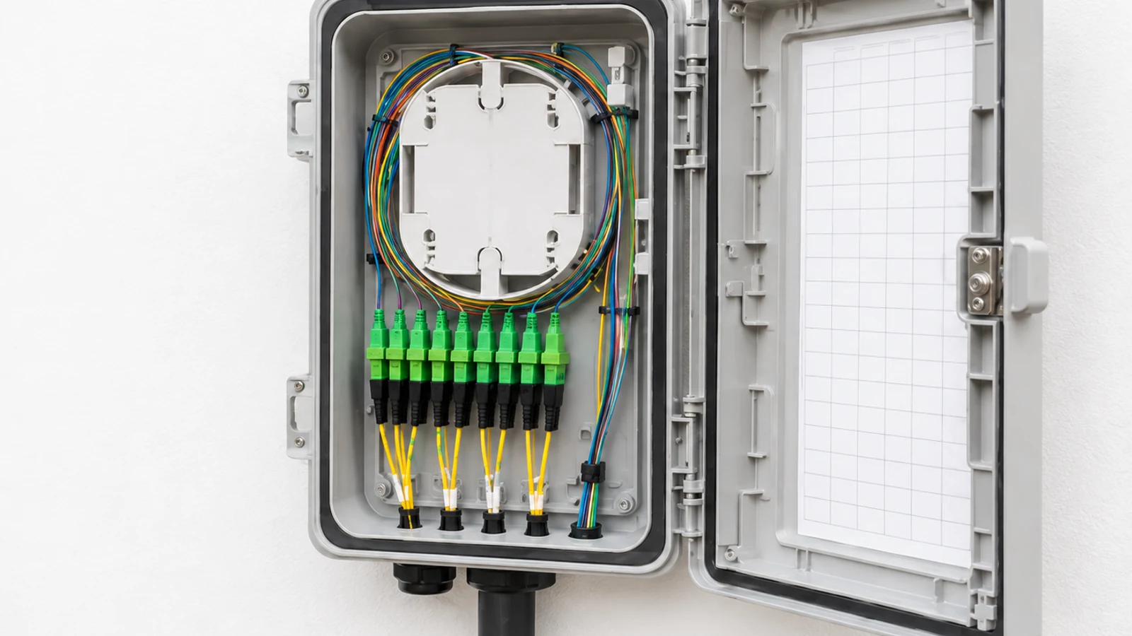
Environmental exposure, route protection, network redundancy, and service access may matter as much as bandwidth.
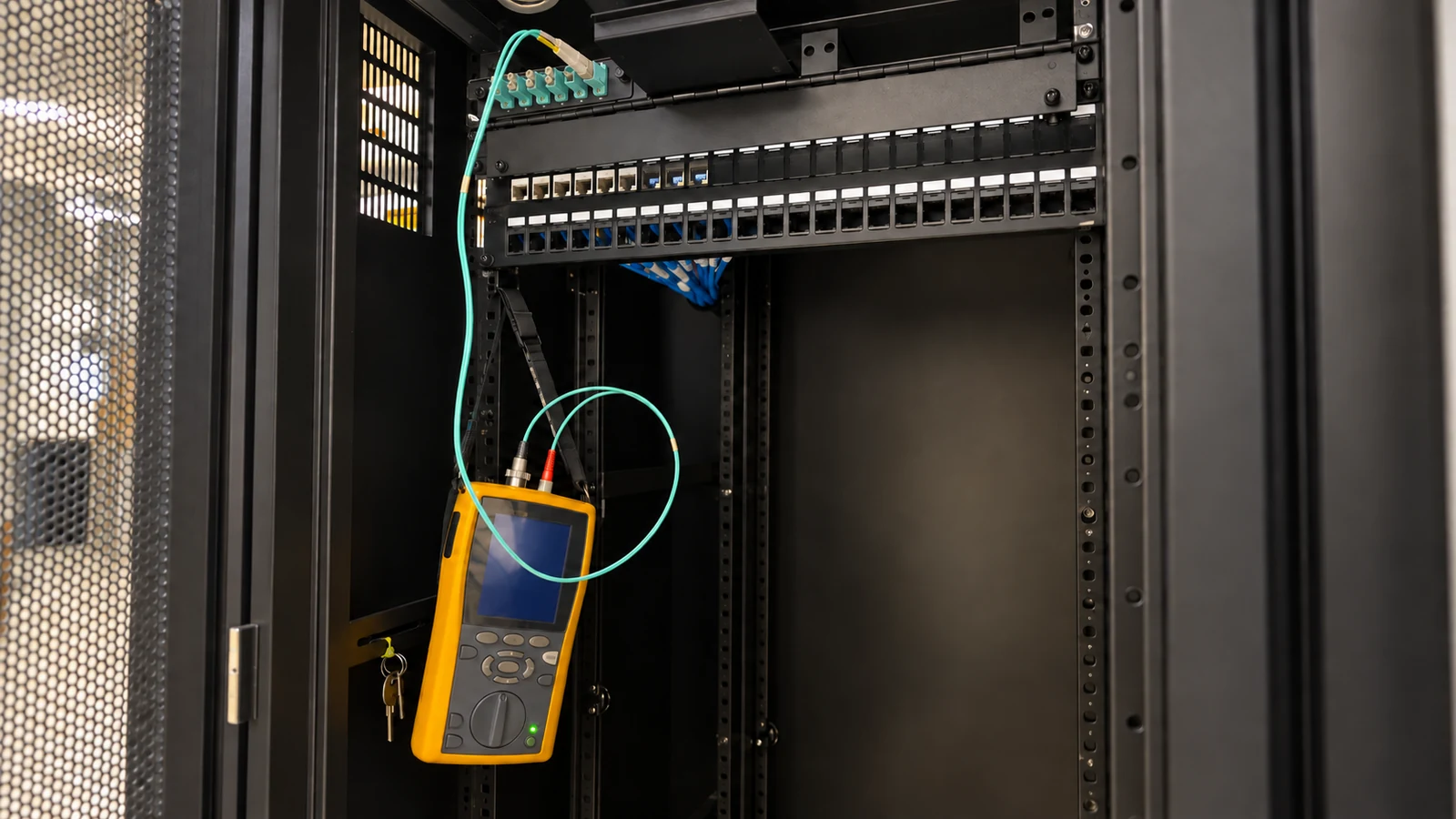
A scalable backbone should reserve strands and enclosure capacity while keeping each MDF-to-IDF link documented and testable.
PROJECT DETAILS
Operational Recommendations
Use distance, optics, application, environment, and lifecycle rather than color or habit.
Reserve strands, enclosure positions, pathway room, and labels for likely future links.
Plan pull points, slack, building entry, trays, strain relief, and enclosure routing.
Specify loss and any trace testing, reference methods, wavelengths, link identifiers, results, and exceptions.
PROJECT DETAILS
This article helps commercial teams understand fiber optic installation systems as a technical and operational decision. It provides a common vocabulary for comparing alternatives before a property-specific design is approved.
Fiber does not deliver endpoint power, so cameras, access devices, and wireless equipment still need local power or appropriate powered infrastructure.
Optics, connectors, polish, and wavelength must match the network design; fiber type alone does not ensure compatibility.
Cleanliness, bend, pulling damage, and enclosure quality can impair a fiber link even when continuity is present.
PROJECT DETAILS
Jacket color is not a substitute for verified media type, optics, distance, and existing network standard.
A later building, redundant link, or system expansion requires another disruptive pull.
Excess tension, sharp bends, or crushed cable can create loss and premature failure.
The link may not operate correctly even though the physical cable reaches both rooms.
A visible light or simple link-up does not document loss, events, margins, or the condition of each strand.
TECHNICAL PLANNING
Define indoor, outdoor, riser, plenum, armored, wet-location, aerial, or underground conditions as applicable to the actual pathway.
Record source and destination, media type, strand count, active pairs, spares, redundancy, and future reservations.
Select splice or connectorized methods, adapters, trays, panels, slack storage, bend control, and service access.
Assign transceivers, wavelength, speed, ports, power, configuration, monitoring, and replacement responsibility.
Specify link identifiers, reference method, wavelengths, pass criteria, bidirectional or trace requirements, files, and exceptions.
PROJECT DETAILS
RELATED SERVICES
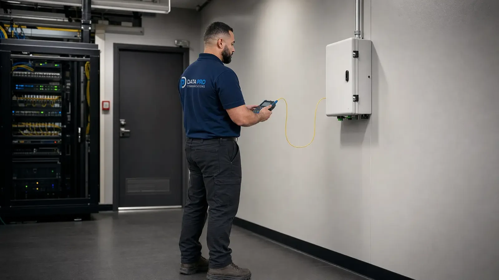
Fiber Optic Services is the primary implementation path when the article findings require a property-specific scope for single-mode and multimode context and strand count and future capacity.
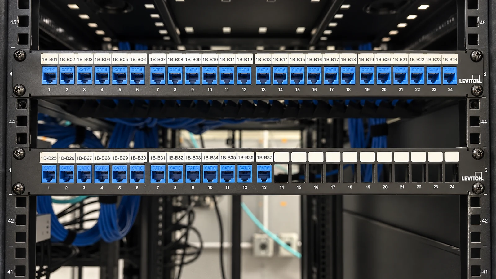
Structured Cabling supports the pathways, labels, and tested physical links involved in route and environmental rating and fiber and strand schedule.
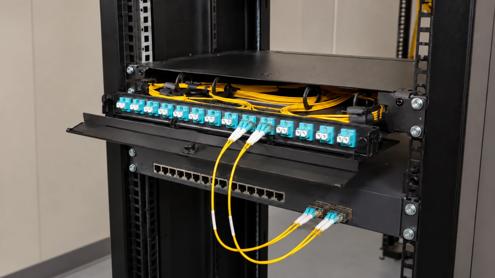
Network Infrastructure addresses switching, power, segmentation, uplinks, accounts, and monitoring where termination and enclosures affects the article decision.
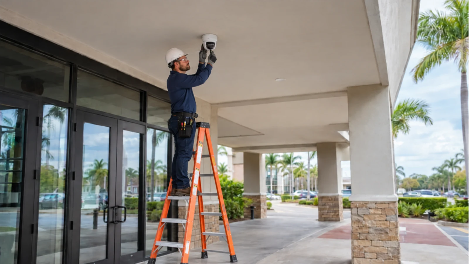
Camera System Upgrades applies when existing equipment must be evaluated against the new requirements for single-mode and multimode context and the stated limitations.
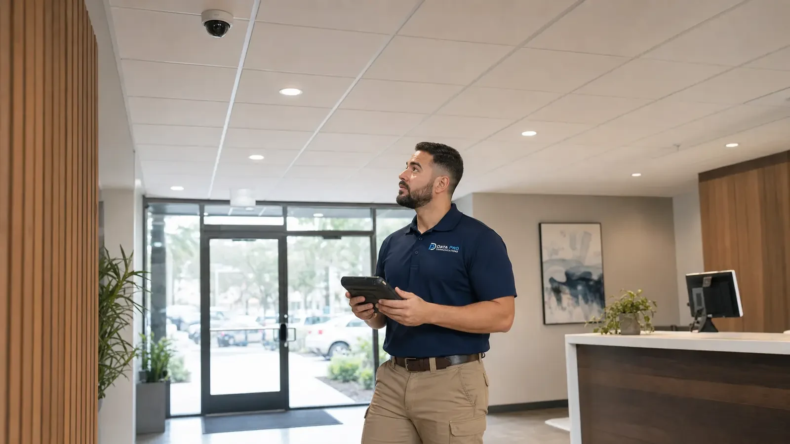
Camera Troubleshooting & Repair uses the documented tests and dependencies in this guide to isolate faults involving loss and trace testing or existing system behavior.
PROJECT PROCESS
Identify the article question, intended users, operating scenario, and the decision the property needs to make about fiber optic installation systems.
Inspect the relevant scenes and dependencies, including route and environmental rating, fiber and strand schedule, and termination and enclosures.
Compare alternatives against the six topic-specific concepts, document limitations, and assign implementation and network responsibilities.
Perform the acceptance checks described in the scope and deliver settings, labels, test results, exceptions, authorized ownership, and service information.
FAQ
A complete fiber system defines more than the cable. It specifies link distance, bandwidth, single-mode or multimode context, strand count, indoor or outdoor construction, pathway, bend and pulling limits, splice or connectorized termination, enclosures, optics responsibility, testing, labels, spare capacity, and service access.
Selection depends on link distance, installed optics, application, existing standards, future capacity, and lifecycle strategy. Jacket color or a general distance rule is not an adequate design basis.
Count active transmit and receive needs, redundancy, growth, spare strands, and any diverse-route strategy. Installing too few strands can make a later expansion depend on another cable pull.
Conduit condition, fill, pull points, tensile load, bend radius, crush risk, building entry, and environmental rating protect the cable during and after installation.
Fusion splicing can support pigtails and repairable enclosure design; preterminated assemblies can reduce field termination but require pathway and length control. The right choice depends on route and service conditions.
Rack and wall enclosures should protect bend radius, adapters, splice trays, slack, and connectors while keeping both ends consistently labeled and accessible.
Continuity is not enough. Loss testing and, where appropriate, trace testing should match the project’s acceptance method, record both ends, and identify abnormal loss or events.
The most common errors include selecting fiber by color alone and installing too few strands. Jacket color is not a substitute for verified media type, optics, distance, and existing network standard.
Use distance, optics, application, environment, and lifecycle rather than color or habit. Reserve strands, enclosure positions, pathway room, and labels for likely future links.
Specify link identifiers, reference method, wavelengths, pass criteria, bidirectional or trace requirements, files, and exceptions.
Fiber does not deliver endpoint power, so cameras, access devices, and wireless equipment still need local power or appropriate powered infrastructure. Optics, connectors, polish, and wavelength must match the network design; fiber type alone does not ensure compatibility.
Survey fiber routes when distance, pathway condition, building entry, media type, strand count, optics, enclosure space, or acceptance testing is not already documented.
Survey fiber routes when distance, pathway condition, building entry, media type, strand count, optics, enclosure space, or acceptance testing is not already documented. The resulting scope should state technical criteria, limitations, responsibilities, and acceptance tests before installation begins.