
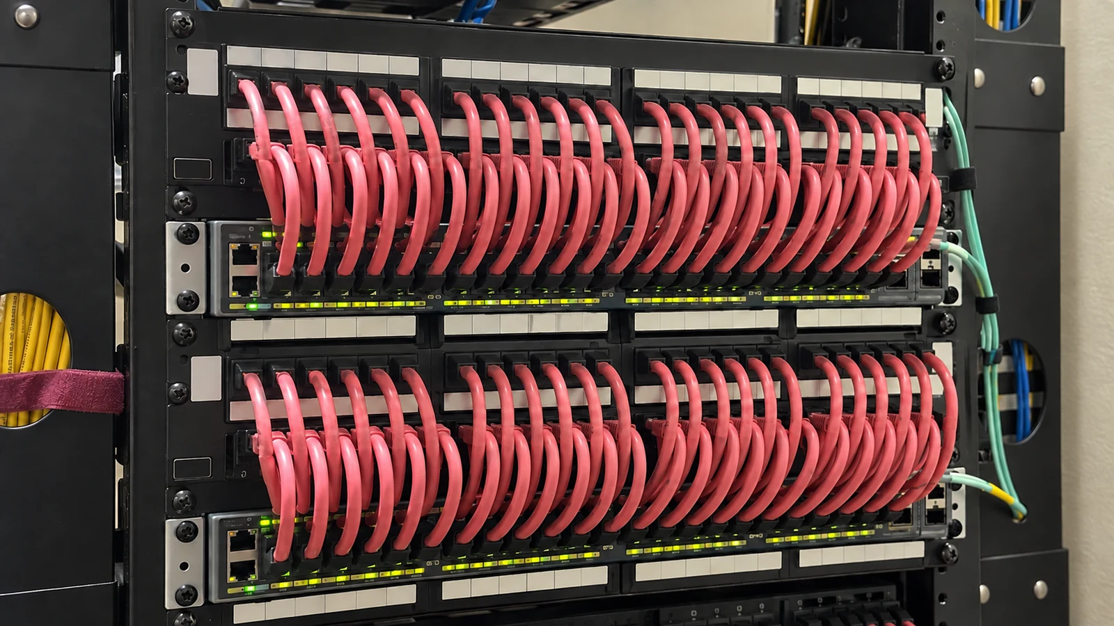
Pathway and Route Planning
Coordinate cable routes, sleeves, trays, supports, accessible transitions, bend limits, separation needs, and entry points around the property layout and construction conditions.
ORGANIZED COMMERCIAL CABLING INFRASTRUCTURE
Structured cabling creates the organized physical layer that connects business networks, cameras, access control, intercom, wireless access points, and other low-voltage systems. Data Pro Communications plans and installs commercial cabling infrastructure for Orlando properties that need clear pathways, serviceable racks, labeled terminations, documented connections, and room to grow.
Projects can include copper and fiber coordination, MDF and IDF planning, patch panels, equipment racks, cable-management hardware, testing, documentation, and moves, additions, or changes. The scope is broader than individual Cat6 or Cat6A drops: it addresses how the complete cabling system is organized, protected, terminated, identified, and handed off.
PROJECT PLANNING
A site survey helps align pathways, telecommunications rooms, rack capacity, device locations, fire-rated boundaries, construction sequencing, and testing requirements before installation begins.
SERVICE OVERVIEW
Commercial structured cabling is a standards-informed system of pathways, spaces, backbone links, horizontal cabling, terminations, racks, patching, labels, tests, and records. The result should make present connections understandable and future work less disruptive. Final media, performance categories, pathways, and test methods are selected from project requirements and field conditions rather than assumed from a generic package.
CORE CAPABILITIES
Coordinate cable routes, sleeves, trays, supports, accessible transitions, bend limits, separation needs, and entry points around the property layout and construction conditions.
Plan main and intermediate distribution spaces around rack placement, backboards, grounding coordination, patching, cable management, service clearances, and realistic growth capacity.
Select copper, fiber, or a coordinated combination according to distance, bandwidth, equipment interfaces, pathway conditions, resilience goals, and future expansion needs.
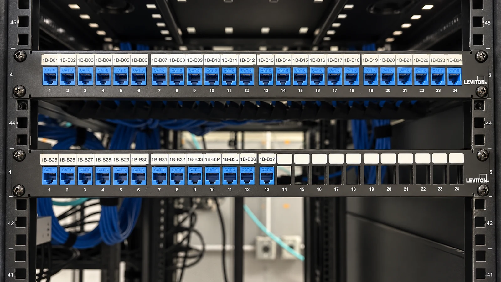
Install and organize racks, patch panels, enclosures, termination hardware, strain relief, and patching so connections remain traceable and serviceable.
Apply a consistent identifier plan, test installed links to the agreed scope, document exceptions, and provide records that support turnover and later changes.
Extend or reorganize existing infrastructure while reviewing pathway capacity, abandoned cabling, rack space, labeling consistency, and effects on active systems.
COMMERCIAL USE CASES
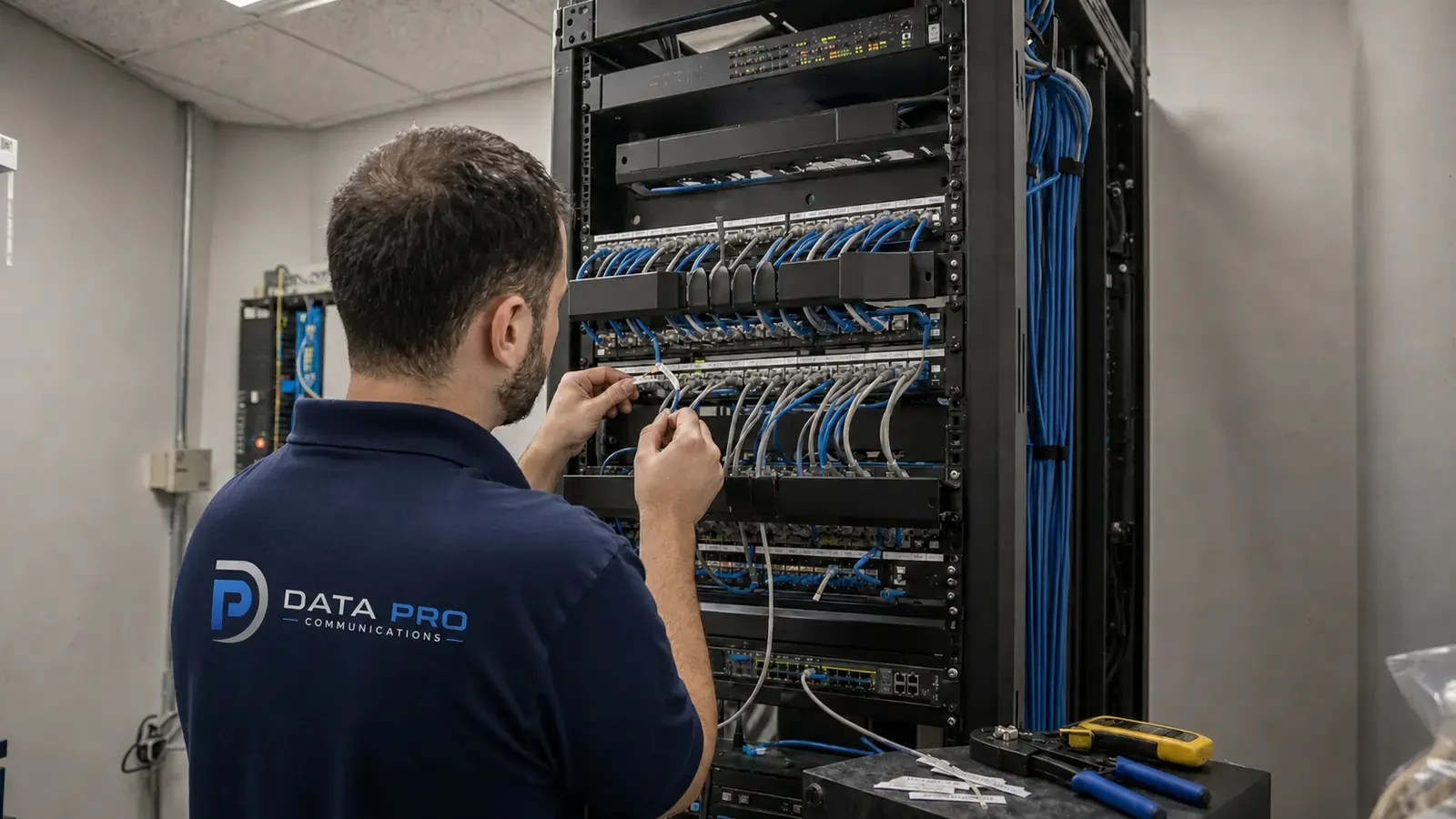
Coordinate guest-service, back-office, surveillance, access, wireless, and operational connections through phased work that respects occupied areas and renovation sequencing.
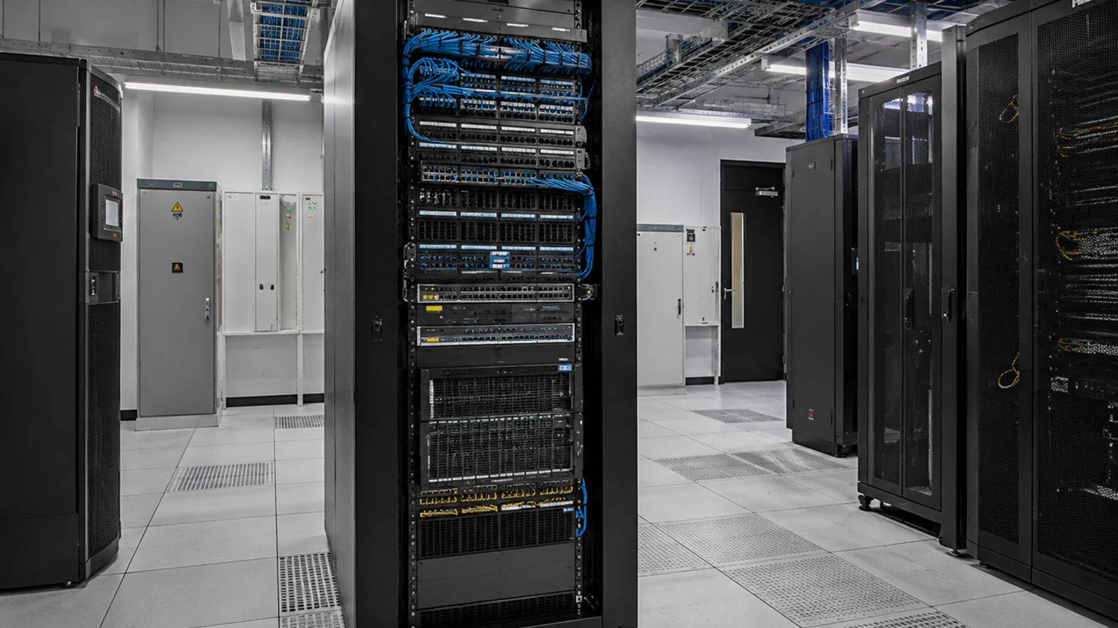
Organize workstation, conference, voice, wireless, camera, and access-control cabling around furniture plans, tenant schedules, telecommunications rooms, and future churn.
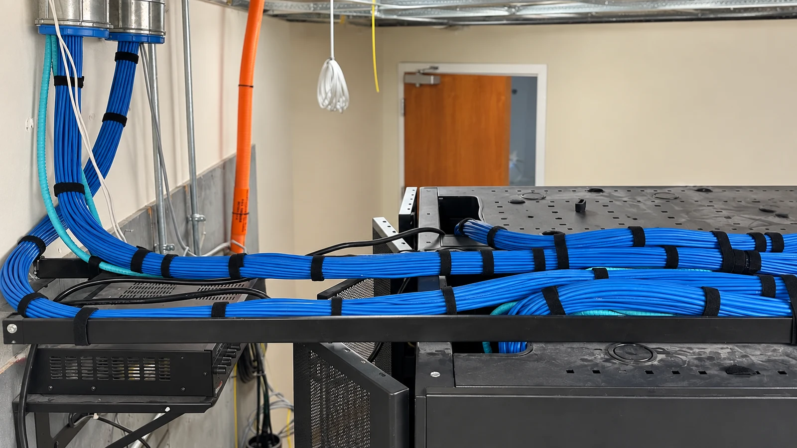
Create repeatable routes and documented distribution points for common-area systems, management offices, amenity spaces, gates, cameras, and building-to-building connections.
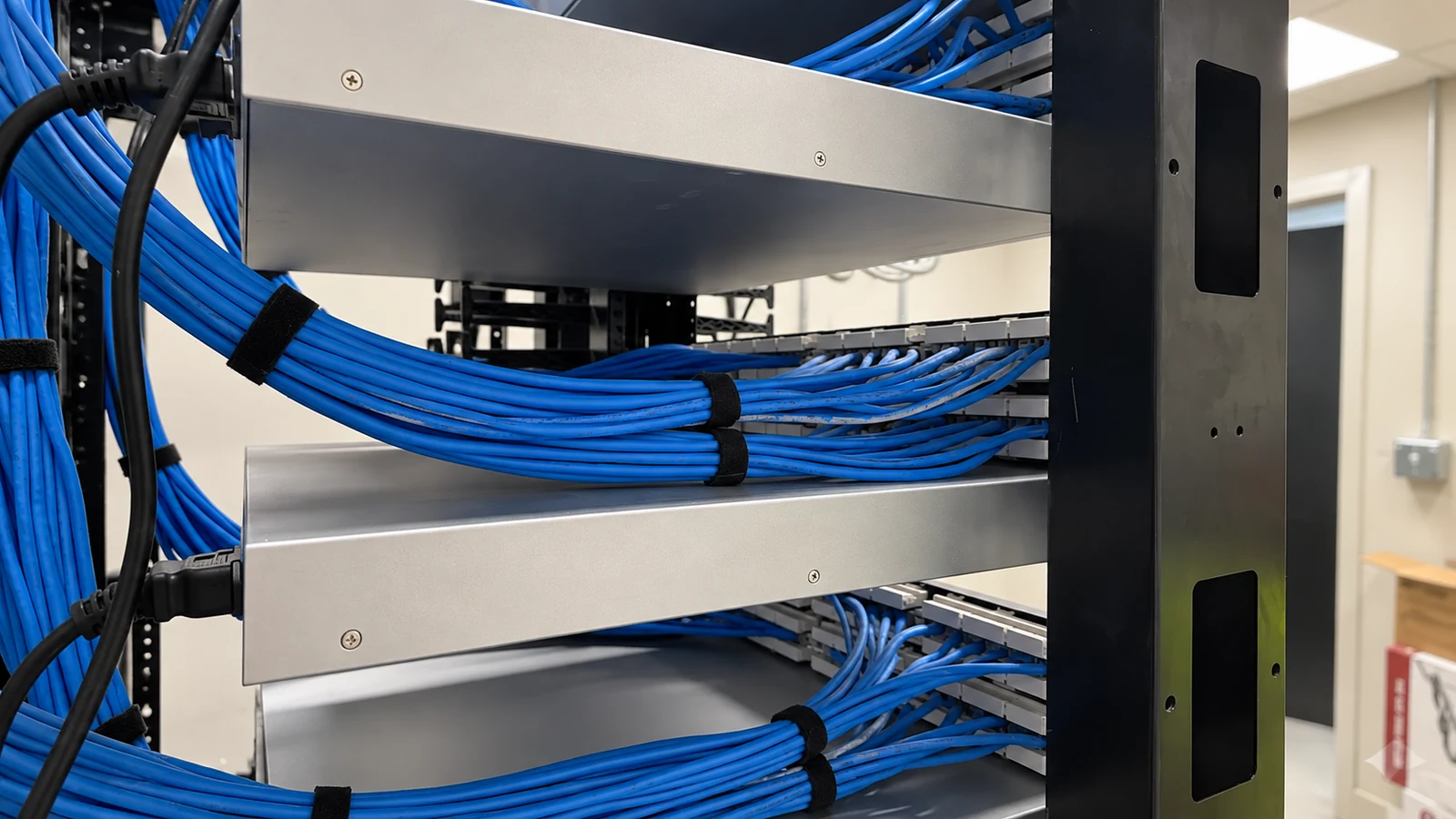
Support long cable runs, elevated pathways, loading zones, work areas, network closets, cameras, access points, and expansion without losing cable identification.
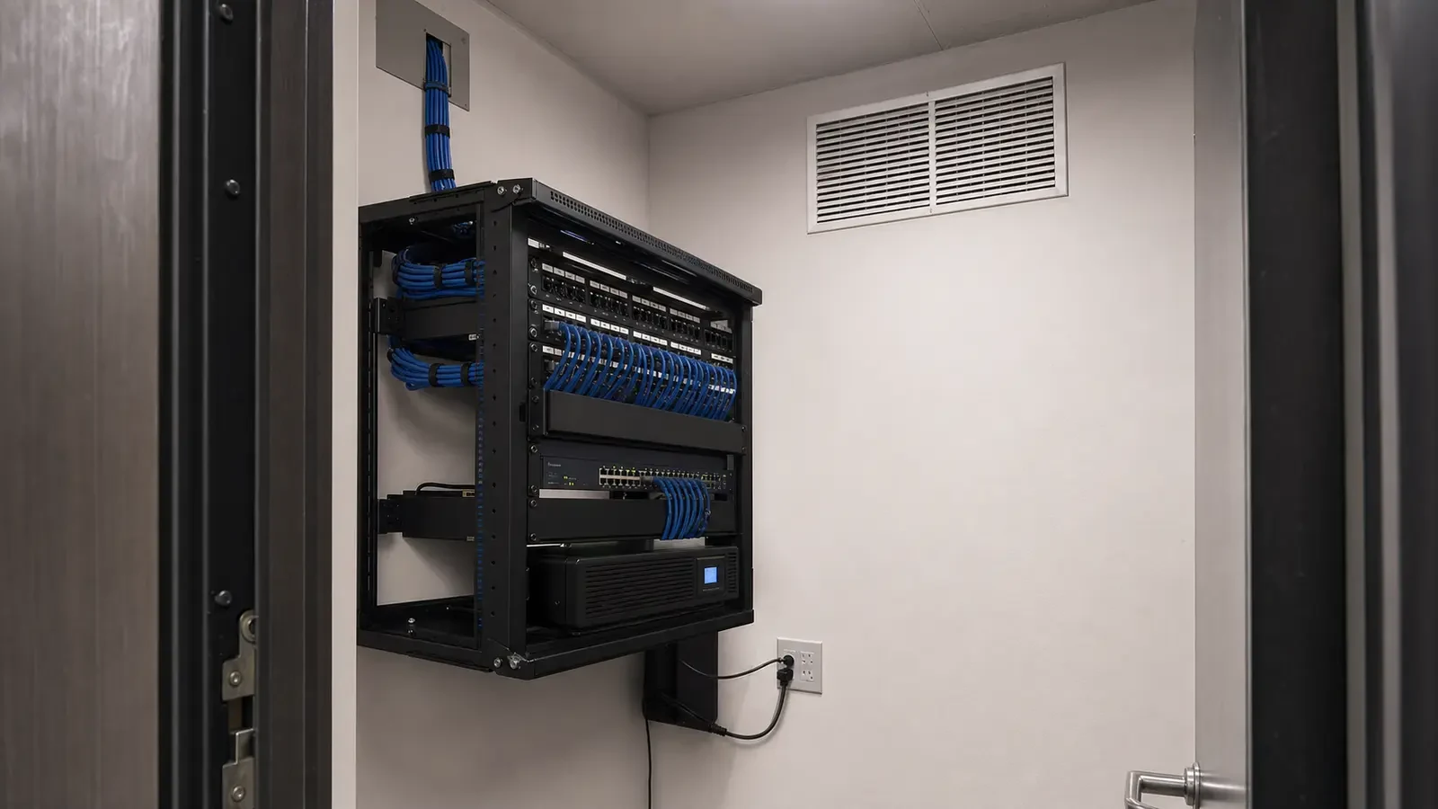
Coordinate pathways and equipment locations around occupied operations, sensitive areas, construction controls, and the project team responsible for system-specific requirements.
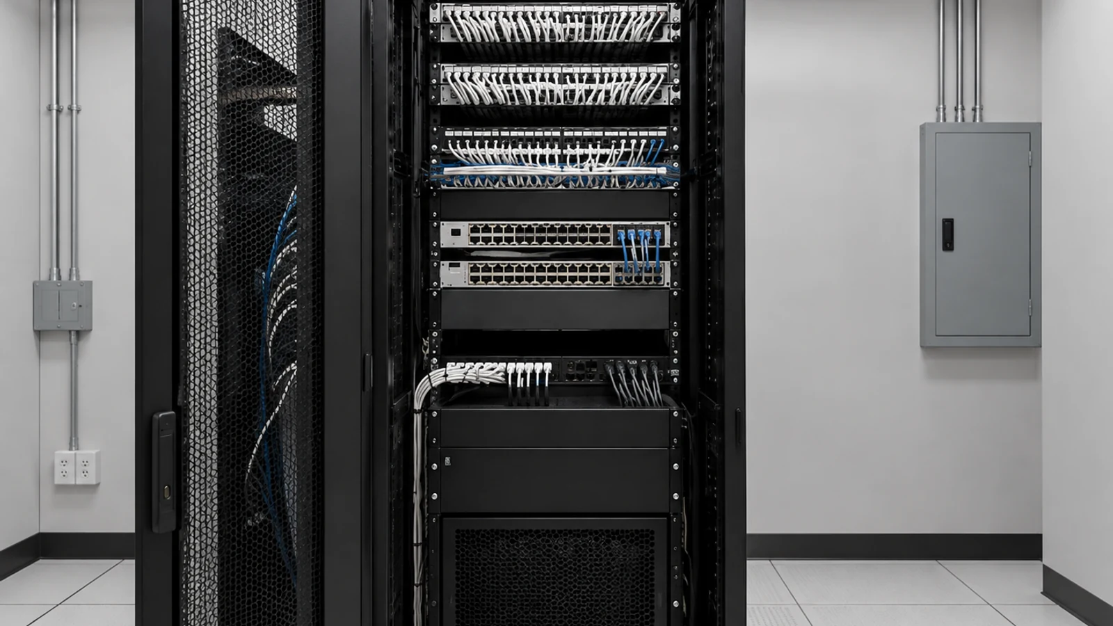
Plan backbone routes, building entrances, distribution rooms, media transitions, spare capacity, and records across multiple structures and property phases.
TECHNICAL PLANNING
Document the rack, panel, port, cable, and destination naming convention before termination. Reserve realistic pathway and rack capacity for known near-term additions instead of filling every available position at turnover.
Final design depends on building pathways, telecommunications-space access, power and environmental conditions for active equipment, equipment interfaces, rated-wall requirements, ceiling access, construction schedules, and owner-approved device locations.
Cabling performance depends on the complete channel, installation conditions, compatible components, and test criteria. Structured cabling does not replace network configuration, electrical work outside authorized low-voltage scope, or manufacturer-specific system programming unless separately included.
ORLANDO SERVICE CONTEXT
Lakehurst and the International Drive area include hospitality properties, commercial offices, retail spaces, managed communities, warehouses, healthcare facilities, construction projects, and multi-building sites with very different access windows and infrastructure histories. A useful cabling plan accounts for occupied spaces, renovation phases, back-of-house routes, shared telecommunications rooms, long property distances, vendor coordination, and the need to keep active operations understandable during changes.
RELATED SERVICES
The following relationships help buyers distinguish adjacent scopes.
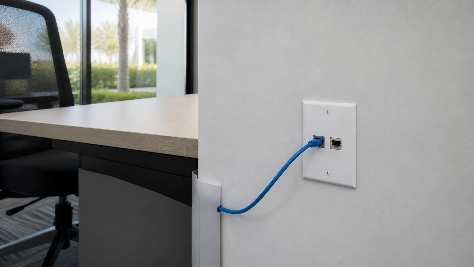
Switching, PoE, VLANs, uplinks, segmentation, and device-capacity planning use the physical cabling layer but remain a distinct network design and configuration scope.
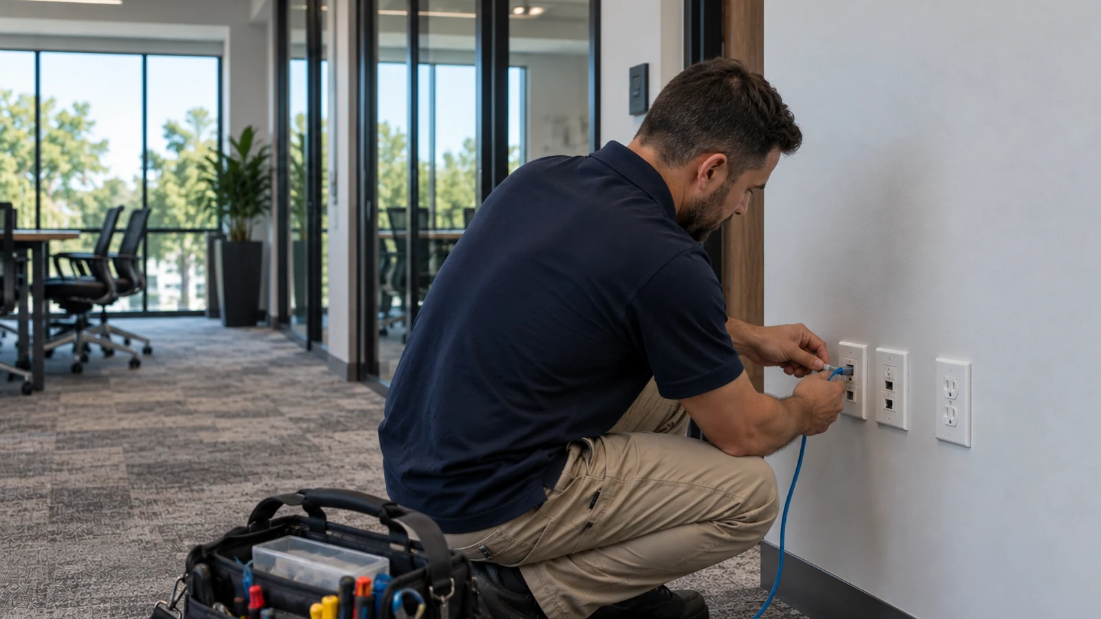
The narrower service-drop page addresses copper category selection and horizontal link delivery; this page owns the broader organized infrastructure intent.
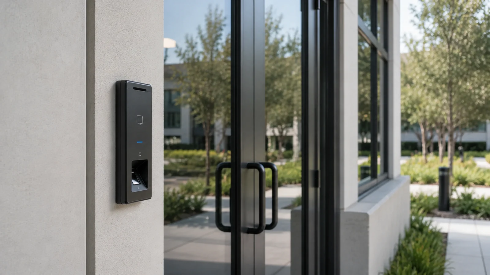
Door controllers, readers, credentials, and field devices depend on coordinated cable routes and documented network or power interfaces.
INDUSTRIES SERVED

Phased pathways and organized back-of-house distribution.

Traceable tenant and common-area infrastructure.

Long-route, backbone, and expansion planning.
PROJECT PROCESS
Review spaces, telecommunications rooms, pathways, active systems, device plans, schedules, and turnover expectations.
Define routes, media, distribution points, racks, patching, labeling, tests, responsibilities, and future-capacity allowances.
Install supports, cable, terminations, management, and labels while coordinating access, construction milestones, and active operations.
Complete agreed tests, correct documented exceptions, deliver identifier and test records, and review the installed organization with the project team.
LICENSED PROJECT SUPPORT
Data Pro Communications - West Orlando is a regional website of Data Pro Communications. Commercial projects are coordinated through the West Orlando / Lakehurst Branch at 5950 Lakehurst Dr, #234, Orlando, FL 32819; (407) 994-3227; FL License #EC13016138. Project requirements, access, schedule, connected systems, and responsibility boundaries are reviewed before the final scope is established.
FAQ
A project may include pathways, copper and fiber cabling, MDF and IDF organization, racks, patch panels, terminations, cable management, labels, testing, documentation, and coordination with connected low-voltage systems. The final scope is defined after reviewing the property and project requirements.
Structured cabling is the broader infrastructure system, including rooms, racks, pathways, backbone media, patching, labels, tests, and records. Cat6 and Cat6A cabling focuses more narrowly on copper category selection and horizontal service-drop links.
Existing cabling may be reusable when its type, condition, routing, terminations, identification, test results, and compatibility with the planned application are acceptable. A field review is needed before reuse is included in the design.
The main distribution frame is the primary telecommunications distribution point, while intermediate distribution frames serve other floors, areas, or buildings. Their locations affect cable distance, backbone design, rack capacity, service access, and future expansion.
Testing and labeling can be included as defined project deliverables. The handoff should identify the label convention, test method, acceptance criteria, exceptions, and records required by the owner or project team.
Yes. A coordinated cabling system can provide organized pathways and connections for networks, cameras, access control, intercom, wireless, and other low-voltage systems, provided each system's media, distance, power, and interface requirements are addressed.
Spare capacity should reflect known growth, likely furniture or device changes, pathway constraints, rack space, port planning, and budget. A practical allowance is project-specific; unused capacity should be intentional and documented.
Many projects can be phased around access windows, active operations, ceiling availability, tenant schedules, and construction milestones. The sequencing plan should protect active services and identify temporary conditions before work starts.
Not automatically. Cabling provides the physical connectivity layer. Switching, VLANs, addressing, wireless configuration, cybersecurity policy, and managed IT support require a separately defined network scope.
Useful information includes floor plans, device counts, room locations, existing rack and pathway details, renovation schedules, connected-system requirements, known service issues, future growth plans, and the parties responsible for network and construction decisions.
Share your property layout, device needs, current cabling conditions, construction schedule, and future growth plans. The Lakehurst team can review the information and define the next appropriate site-survey step.