
Site-Specific Planning
Views and pathways are selected around the technical decision and the actual commercial property, not a generic device count.
COMMERCIAL SECURITY AND LOW-VOLTAGE RESOURCE
Structured cabling is the organized physical foundation that connects work areas and devices to telecom rooms through planned copper and fiber pathways, patch panels, labels, and test records. Its value is predictable service and change, not simply a bundle of category-rated cables.
This guide explains the technical variables, tradeoffs, failure modes, and contractor questions that matter for structured cabling systems in orlando. Use it to prepare a scope, then verify property-specific conditions before implementation.
PROJECT DETAILS
Views and pathways are selected around the technical decision and the actual commercial property, not a generic device count.
Cameras, recording, cabling, network, access and related dependencies are reviewed as one operating system.
Work zones and cutovers are organized around approved access, occupancy and network windows.
Labels, device schedules, test results, user ownership and exceptions support ongoing service.
Commercial low-voltage work is provided under FL License #EC13016138.
SERVICE OVERVIEW
Structured cabling is the organized physical foundation that connects work areas and devices to telecom rooms through planned copper and fiber pathways, patch panels, labels, and test records. Its value is predictable service and change, not simply a bundle of category-rated cables.
The decision is complete only when the required outcome, field conditions, infrastructure, operating owner, limitations, and acceptance method agree with one another.
CORE CAPABILITIES
Voice, data, wireless, cameras, access devices, and building systems have different link, power, and availability needs.
Tray, conduit, sleeves, supports, penetrations, and restoration must suit the building and responsible trade boundaries.
Copper channel length, conductor size, bundling, temperature, and device power affect design.
MDF-to-IDF and building-to-building links require fiber type, strand count, pathway, termination, optics, testing, and spare-capacity decisions.
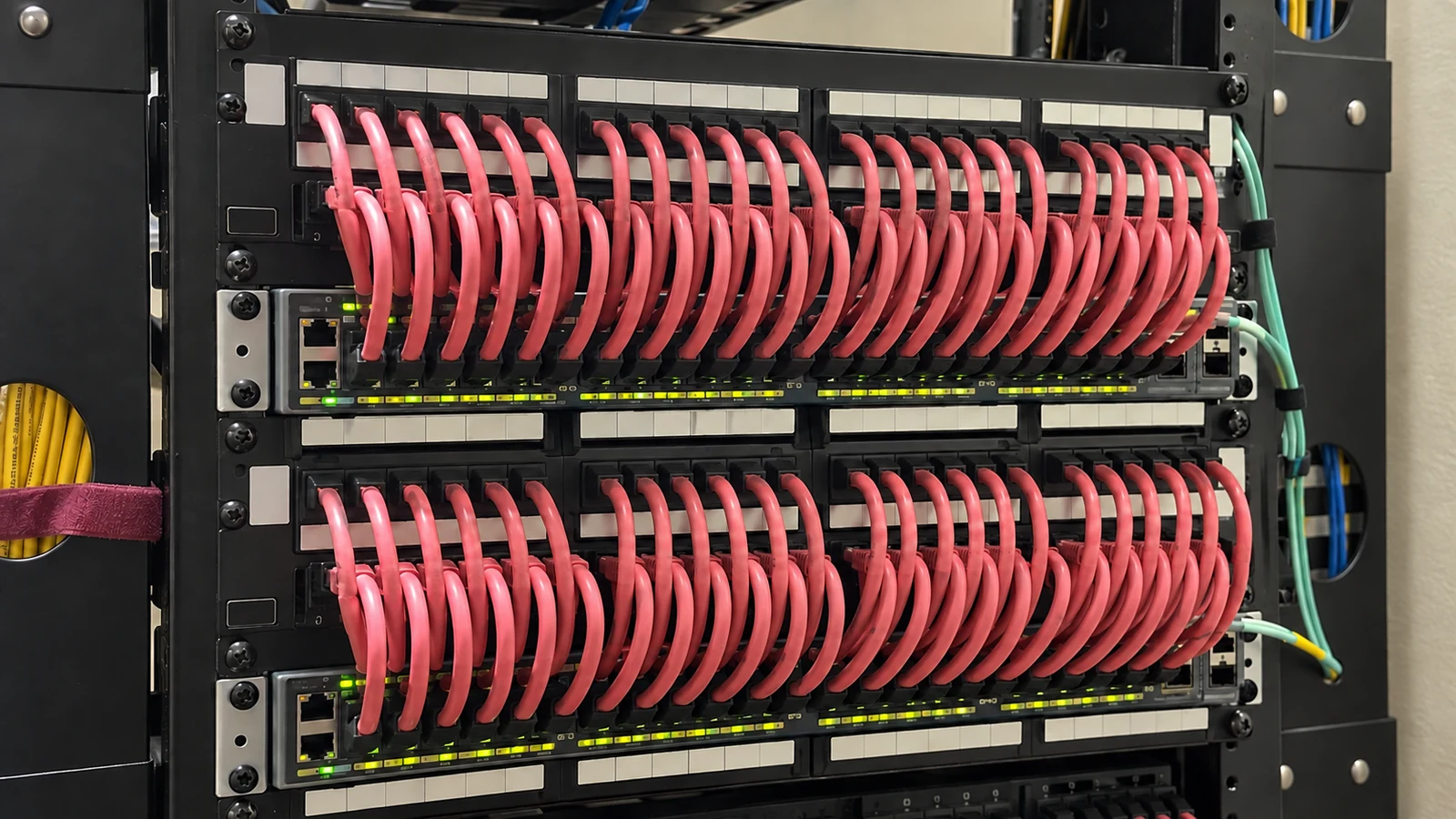
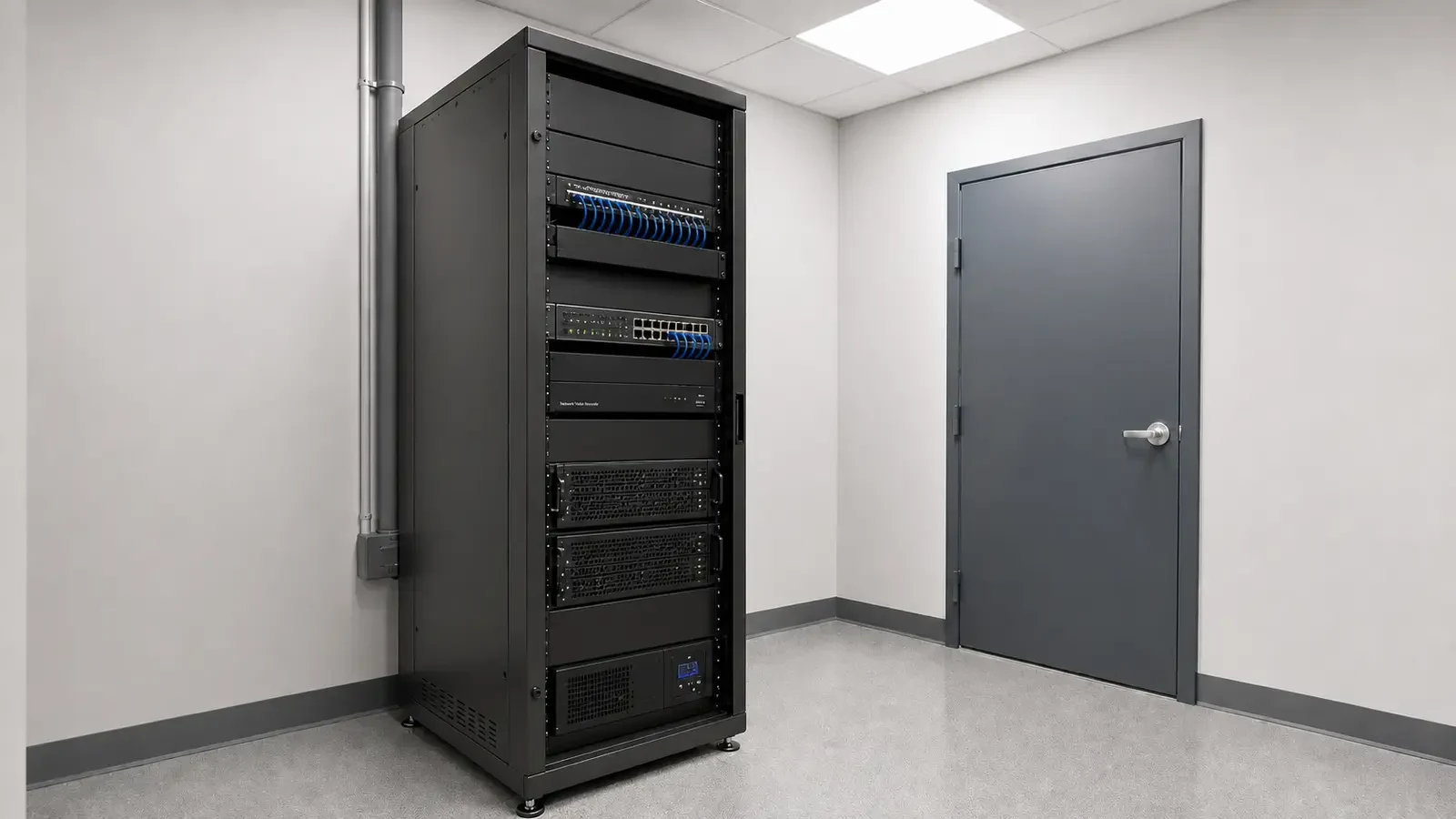
Patch panels, switches, managers, UPS or PDU equipment, grounding, airflow, and service clearance should be arranged as one operating system.
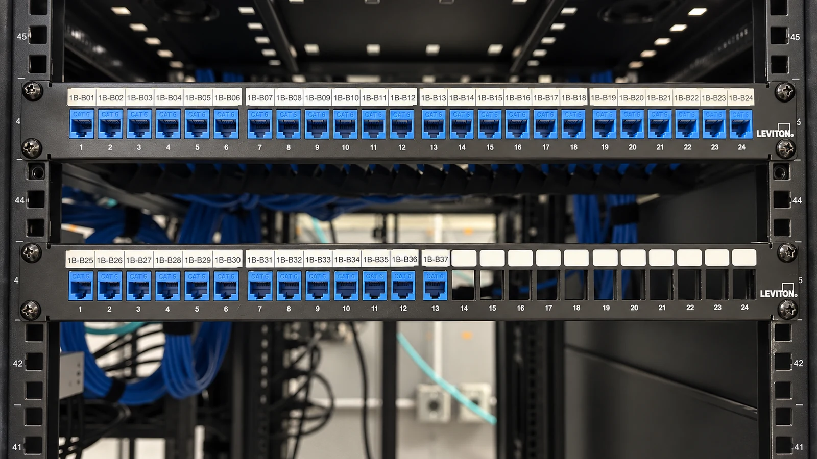
Permanent-link test results, cable and port identifiers, rack elevations, pathways, and exceptions allow future technicians to change or troubleshoot the system without rediscovery.
ORLANDO SERVICE CONTEXT
Western Greater Orlando properties range from visitor-facing hospitality and retail to offices, healthcare, warehouses, managed communities and active construction. The correct answer changes with occupancy, work windows, weather exposure, network ownership and the physical distances at the actual site.
Orlando offices, hotels, warehouses, schools, and managed properties often combine renovations with active operations. Cabling design should coordinate pathways, telecom-room space, copper distance, PoE, fiber backbones, firestopping, labeling, testing, and future moves before ceilings or hardscape close access.
TECHNICAL PLANNING
Application and bandwidth requirements
Voice, data, wireless, cameras, access devices, and building systems have different link, power, and availability needs. The cabling scope should identify applications without promising performance from cable category alone.
Pathway and firestopping conditions
Tray, conduit, sleeves, supports, penetrations, and restoration must suit the building and responsible trade boundaries. Pathway capacity and access should be checked before cable is pulled.
Copper distance and PoE load
Copper channel length, conductor size, bundling, temperature, and device power affect design. Remote devices or separate buildings may need an IDF or fiber instead of an overlong copper run.
Backbone and fiber needs
MDF-to-IDF and building-to-building links require fiber type, strand count, pathway, termination, optics, testing, and spare-capacity decisions.
Rack, patching, and power layout
Patch panels, switches, managers, UPS or PDU equipment, grounding, airflow, and service clearance should be arranged as one operating system.
Labeling, testing, and as-built records
Permanent-link test results, cable and port identifiers, rack elevations, pathways, and exceptions allow future technicians to change or troubleshoot the system without rediscovery.
PROJECT DETAILS
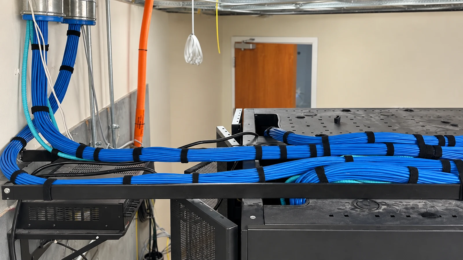
Coordinate outlets, furniture, wireless locations, telecom-room readiness, rack layout, and test records before finishes close pathways.
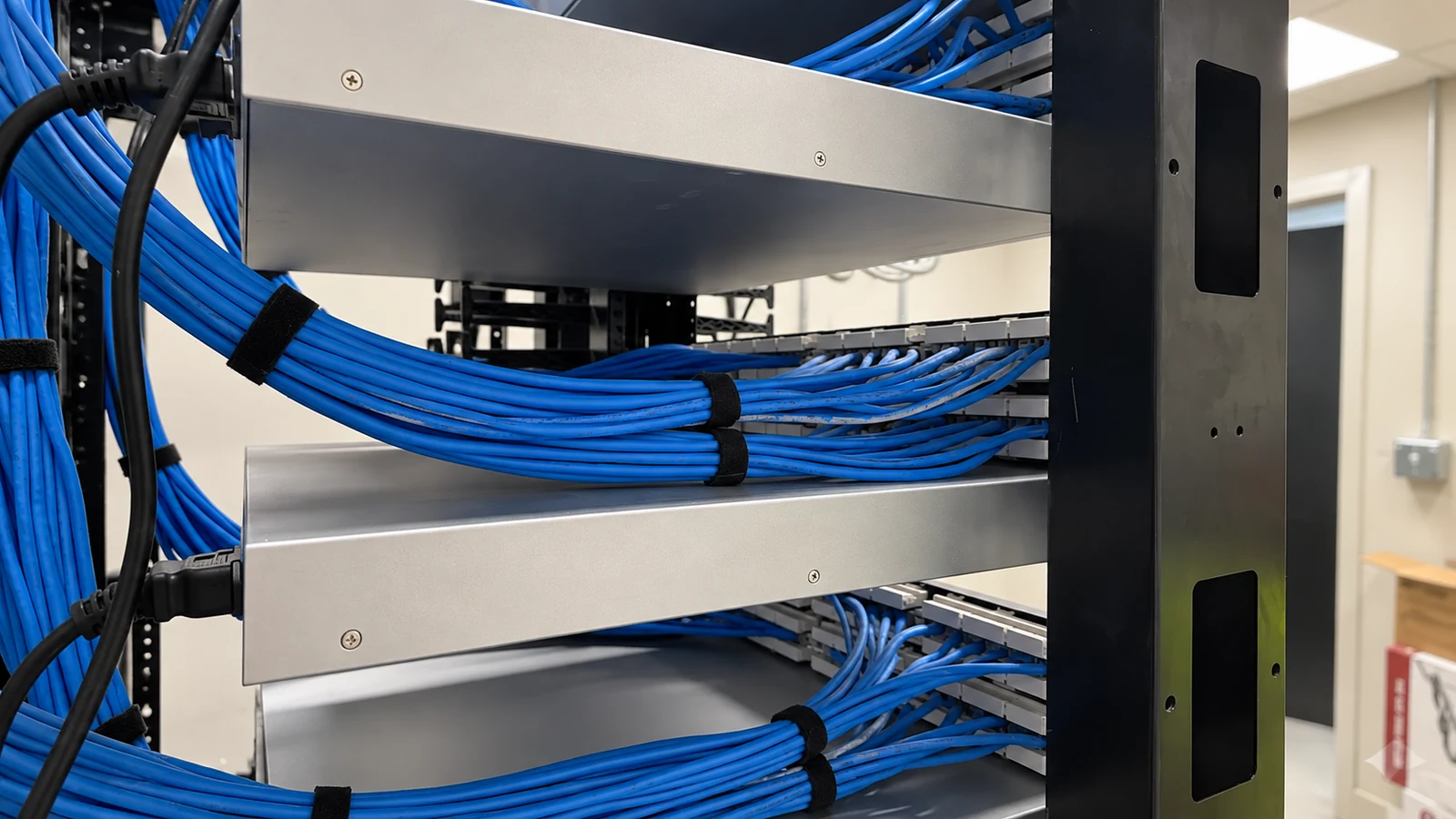
High ceilings, long routes, lift access, PoE, heat, dust, and IDF placement affect the cable and service plan.
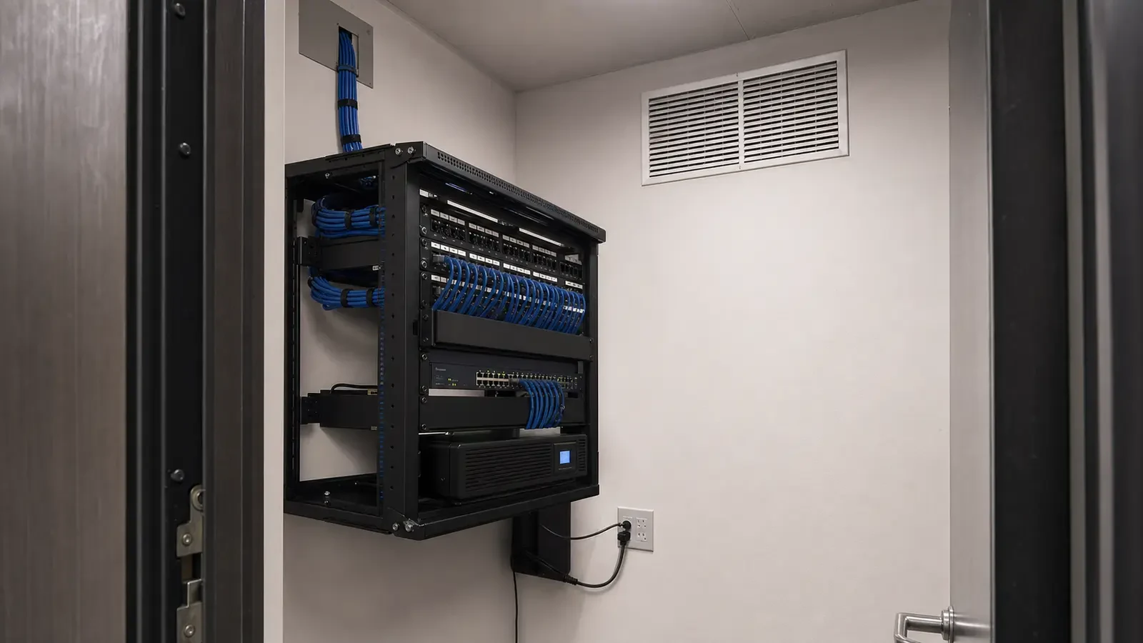
Phase guest floors and back-of-house areas while preserving active services and keeping room, floor, and rack labels consistent.
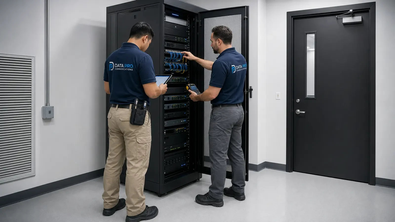
Backbone capacity, room cooling, power, security, and future classroom or wireless growth should be planned together.
PROJECT DETAILS
Operational Recommendations
Confirm routes, supports, sleeves, access, fill, and restoration before ordering cable.
Use copper for appropriate device links and fiber where distance, building separation, or capacity requires it.
Reserve patching, PoE, power, airflow, and growth space for the devices the cabling will serve.
Deliver permanent-link results, port schedules, rack elevations, pathways, and documented exceptions.
PROJECT DETAILS
This article helps commercial teams understand structured cabling systems in orlando as a technical and operational decision. It provides a common vocabulary for comparing alternatives before a property-specific design is approved.
A cable category marking does not guarantee application performance without compatible components, compliant installation, and appropriate testing.
Copper still has distance, environmental, and power-delivery constraints; adding a higher category does not remove them.
Existing pathways and cables can be reused only after route, condition, capacity, labeling, and performance are verified.
PROJECT DETAILS
Routes become inaccessible, overcrowded, unsupported, or dependent on unapproved penetrations.
Cable, jacks, patch panels, cords, and installation practices may not support the intended tested channel.
Crowding damages serviceability, bend control, airflow, and future expansion.
Continuity alone does not show whether an installed copper link meets the required transmission performance.
Moves, changes, incident response, and troubleshooting require unnecessary rediscovery.
TECHNICAL PLANNING
Confirm room access, rack location, power, grounding, environmental conditions, security, and service clearance.
Coordinate tray, conduit, J-hooks, sleeves, penetrations, workstation routes, and device mounting.
Check channel length, cable construction, bundling, temperature, switch budget, and endpoint power.
Define media type, strand count, routes, enclosures, optics responsibility, testing, and spare capacity.
Use a consistent label plan, permanent-link or fiber tests, rack schedules, as-builts, and exception records.
PROJECT DETAILS
RELATED SERVICES
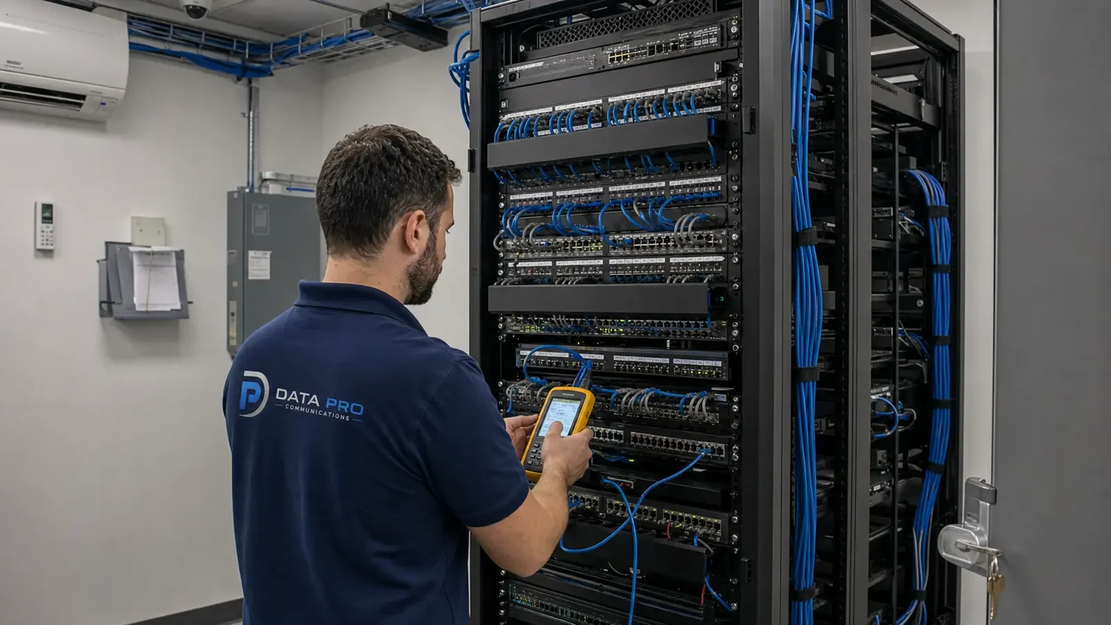
Structured Cabling is the primary implementation path when the article findings require a property-specific scope for application and bandwidth requirements and pathway and firestopping conditions.
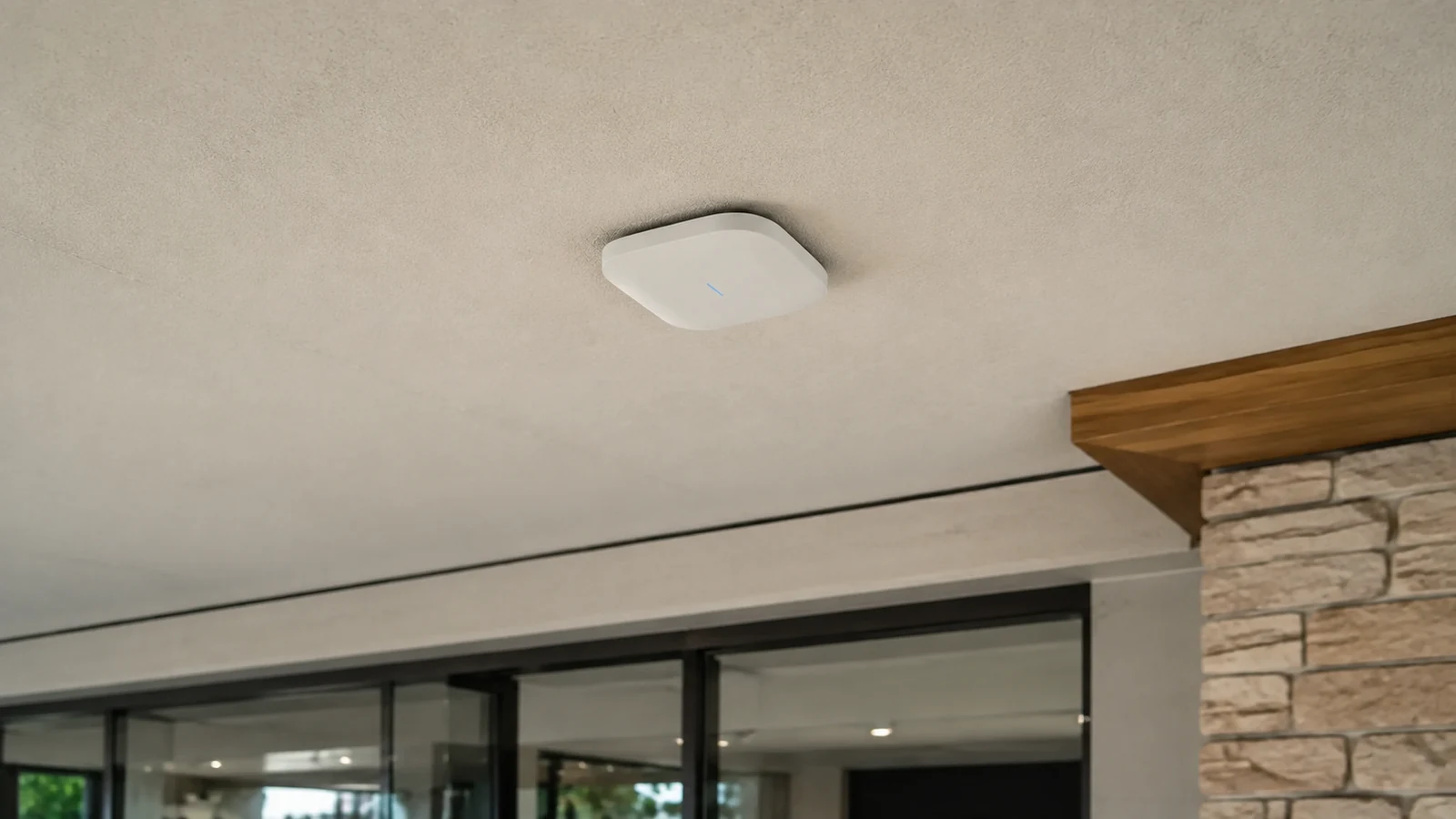
Network Infrastructure addresses switching, power, segmentation, uplinks, accounts, and monitoring where copper and poe design affects the article decision.
Camera System Upgrades applies when existing equipment must be evaluated against the new requirements for application and bandwidth requirements and the stated limitations.
Camera Troubleshooting & Repair uses the documented tests and dependencies in this guide to isolate faults involving administration and testing or existing system behavior.
PROJECT PROCESS
Identify the article question, intended users, operating scenario, and the decision the property needs to make about structured cabling systems in orlando.
Inspect the relevant scenes and dependencies, including telecom-room readiness, horizontal pathways, and copper and poe design.
Compare alternatives against the six topic-specific concepts, document limitations, and assign implementation and network responsibilities.
Perform the acceptance checks described in the scope and deliver settings, labels, test results, exceptions, authorized ownership, and service information.
FAQ
Structured cabling is the organized physical foundation that connects work areas and devices to telecom rooms through planned copper and fiber pathways, patch panels, labels, and test records. Its value is predictable service and change, not simply a bundle of category-rated cables.
Voice, data, wireless, cameras, access devices, and building systems have different link, power, and availability needs. The cabling scope should identify applications without promising performance from cable category alone.
Tray, conduit, sleeves, supports, penetrations, and restoration must suit the building and responsible trade boundaries. Pathway capacity and access should be checked before cable is pulled.
Copper channel length, conductor size, bundling, temperature, and device power affect design. Remote devices or separate buildings may need an IDF or fiber instead of an overlong copper run.
MDF-to-IDF and building-to-building links require fiber type, strand count, pathway, termination, optics, testing, and spare-capacity decisions.
Patch panels, switches, managers, UPS or PDU equipment, grounding, airflow, and service clearance should be arranged as one operating system.
Permanent-link test results, cable and port identifiers, rack elevations, pathways, and exceptions allow future technicians to change or troubleshoot the system without rediscovery.
The most common errors include pulling cable before pathway coordination and mixing unsupported components. Routes become inaccessible, overcrowded, unsupported, or dependent on unapproved penetrations.
Confirm routes, supports, sleeves, access, fill, and restoration before ordering cable. Use copper for appropriate device links and fiber where distance, building separation, or capacity requires it.
Use a consistent label plan, permanent-link or fiber tests, rack schedules, as-builts, and exception records.
A cable category marking does not guarantee application performance without compatible components, compliant installation, and appropriate testing. Copper still has distance, environmental, and power-delivery constraints; adding a higher category does not remove them.
Survey the property when pathways, room readiness, distance, PoE, backbone, rack capacity, or testing requirements are not documented and accessible.
Survey the property when pathways, room readiness, distance, PoE, backbone, rack capacity, or testing requirements are not documented and accessible. The resulting scope should state technical criteria, limitations, responsibilities, and acceptance tests before installation begins.