
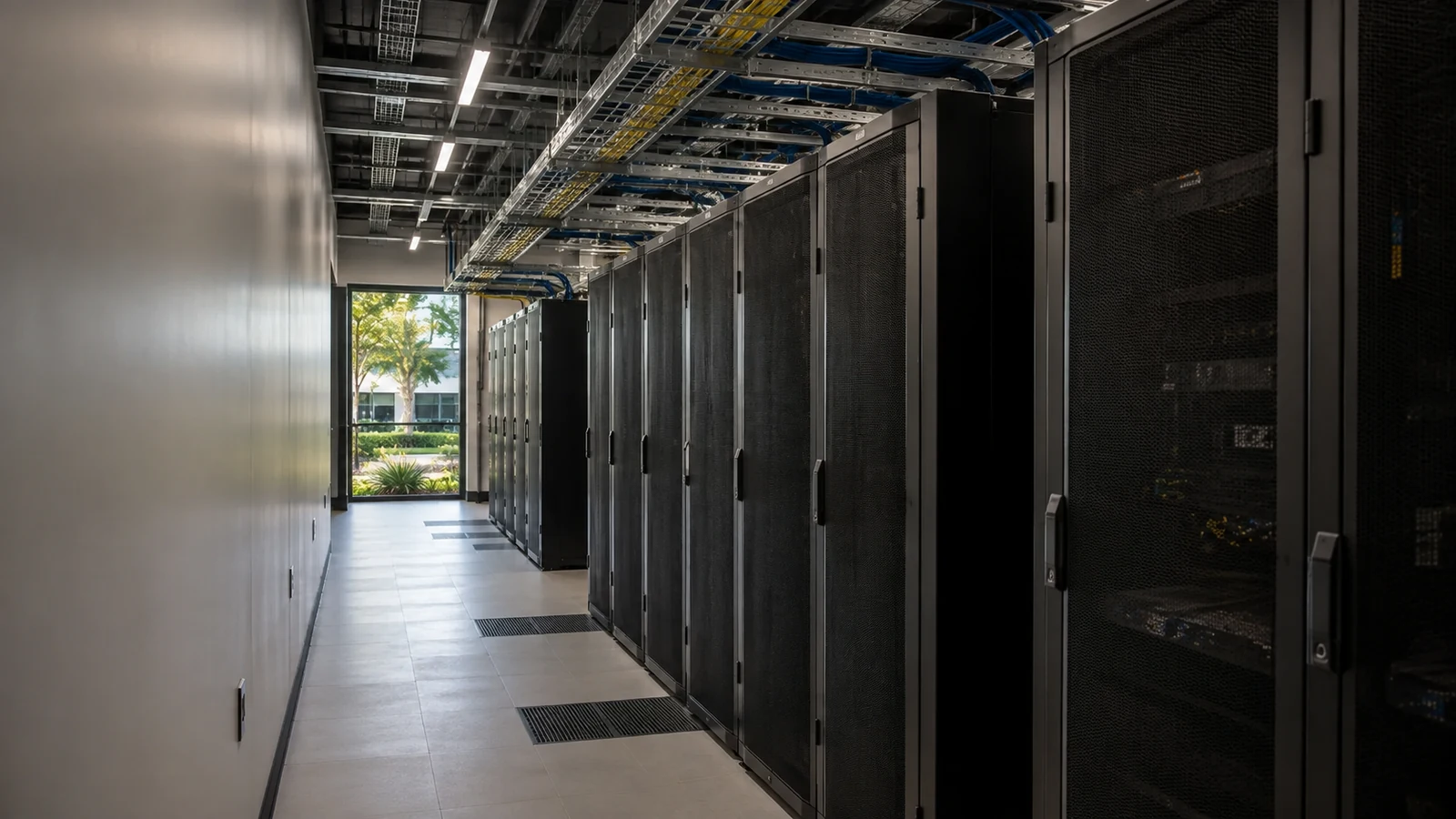
Site-Specific Planning
Views and pathways are selected around the technical decision and the actual commercial property, not a generic device count.
COMMERCIAL SECURITY AND LOW-VOLTAGE RESOURCE
A network rack is an operating workspace for patching, switching, power, and service, not just a metal frame. Correct planning covers rack units, usable depth, equipment weight, patch-panel order, PoE load, UPS and PDU needs, heat, grounding, cable management, clearances, labels, and expansion.
This guide explains the technical variables, tradeoffs, failure modes, and contractor questions that matter for network rack installation. Use it to prepare a scope, then verify property-specific conditions before implementation.
PROJECT DETAILS
Views and pathways are selected around the technical decision and the actual commercial property, not a generic device count.
Cameras, recording, cabling, network, access and related dependencies are reviewed as one operating system.
Work zones and cutovers are organized around approved access, occupancy and network windows.
Labels, device schedules, test results, user ownership and exceptions support ongoing service.
Commercial low-voltage work is provided under FL License #EC13016138.
SERVICE OVERVIEW
A network rack is an operating workspace for patching, switching, power, and service, not just a metal frame. Correct planning covers rack units, usable depth, equipment weight, patch-panel order, PoE load, UPS and PDU needs, heat, grounding, cable management, clearances, labels, and expansion.
The decision is complete only when the required outcome, field conditions, infrastructure, operating owner, limitations, and acceptance method agree with one another.
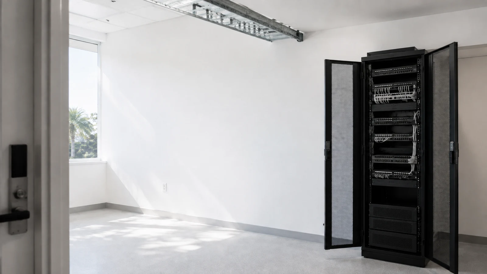
CORE CAPABILITIES
Count rack units but also verify usable depth, rail type, door clearance, cable bend space, equipment weight, and the dimensions of switches, UPS units, patch panels, shelves, and future equipment.
Group patching logically and keep patch-cord paths short and traceable.
Camera, wireless, phone, and access-device loads affect switch count, power budget, heat, uplinks, and UPS runtime.
Define input power, branch-circuit responsibility, receptacles, PDU arrangement, shutdown behavior, expected runtime, and equipment that should or should not be backed up.
Equipment heat, room ventilation, grounding and bonding, front and rear access, and safe service clearance depend on the actual room and installed load.
Vertical and horizontal managers, pathway entry, service loops, rack elevations, device names, port labels, and reserved rack and switch capacity keep the rack maintainable.
ORLANDO SERVICE CONTEXT
Western Greater Orlando properties range from visitor-facing hospitality and retail to offices, healthcare, warehouses, managed communities and active construction. The correct answer changes with occupancy, work windows, weather exposure, network ownership and the physical distances at the actual site.
Orlando telecom spaces can range from conditioned rooms to warehouse closets and renovation-era wall cabinets. Confirm room access, moisture and heat conditions, wall or floor support, electrical scope, cable entry, and service aisle before choosing the rack.
TECHNICAL PLANNING
Rack size, depth, and equipment fit
Count rack units but also verify usable depth, rail type, door clearance, cable bend space, equipment weight, and the dimensions of switches, UPS units, patch panels, shelves, and future equipment.
Patch-panel and switch layout
Group patching logically and keep patch-cord paths short and traceable. Layout should support moves and changes without blocking ports, fans, or equipment removal.
PoE load and switching
Camera, wireless, phone, and access-device loads affect switch count, power budget, heat, uplinks, and UPS runtime. Port count alone is not a complete switch plan.
UPS, PDU, and electrical coordination
Define input power, branch-circuit responsibility, receptacles, PDU arrangement, shutdown behavior, expected runtime, and equipment that should or should not be backed up.
Thermal load, grounding, and clearance
Equipment heat, room ventilation, grounding and bonding, front and rear access, and safe service clearance depend on the actual room and installed load.
Cable management, labels, and growth
Vertical and horizontal managers, pathway entry, service loops, rack elevations, device names, port labels, and reserved rack and switch capacity keep the rack maintainable.
PROJECT DETAILS
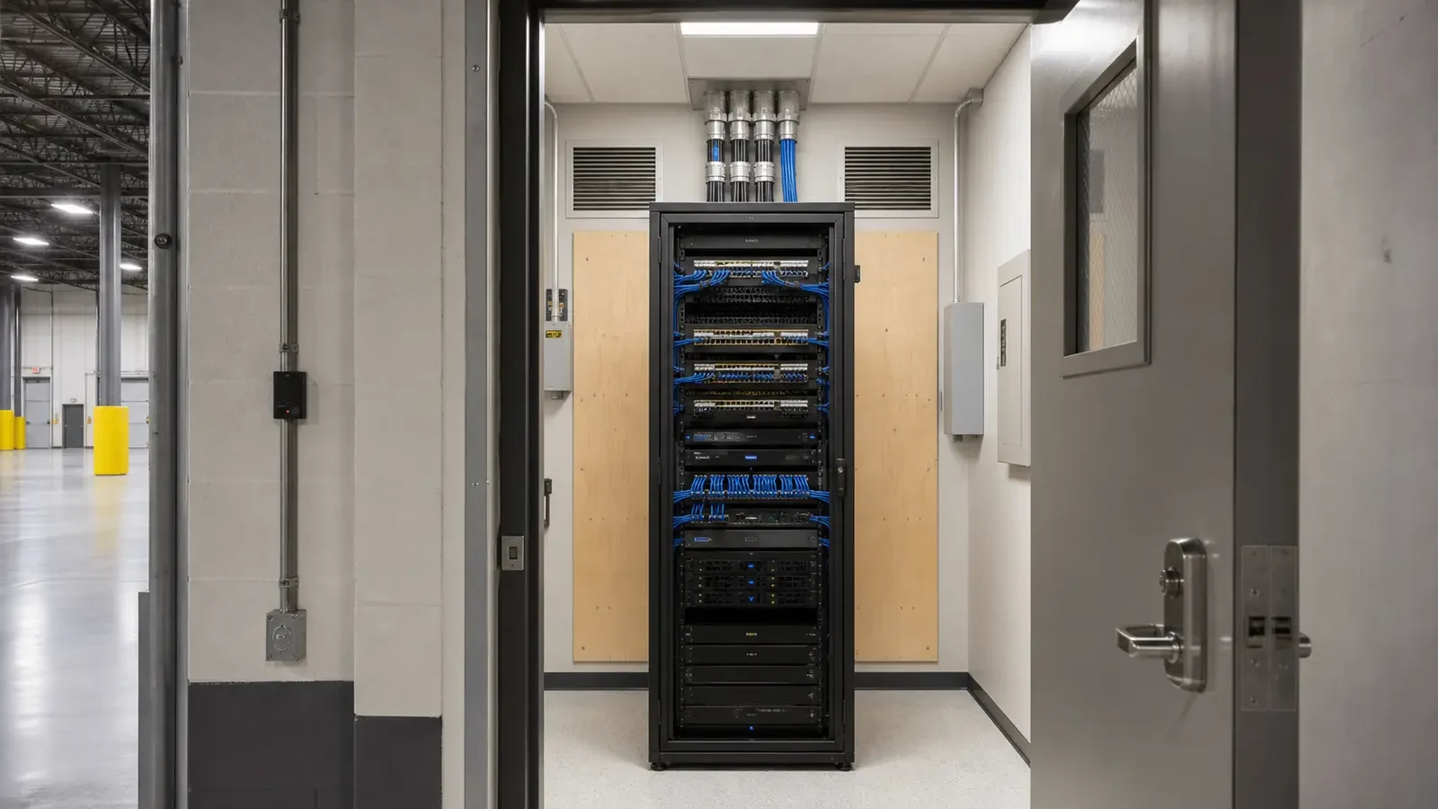
Depth, wall support, swing clearance, patching, UPS location, and heat can matter more than nominal rack-unit count.
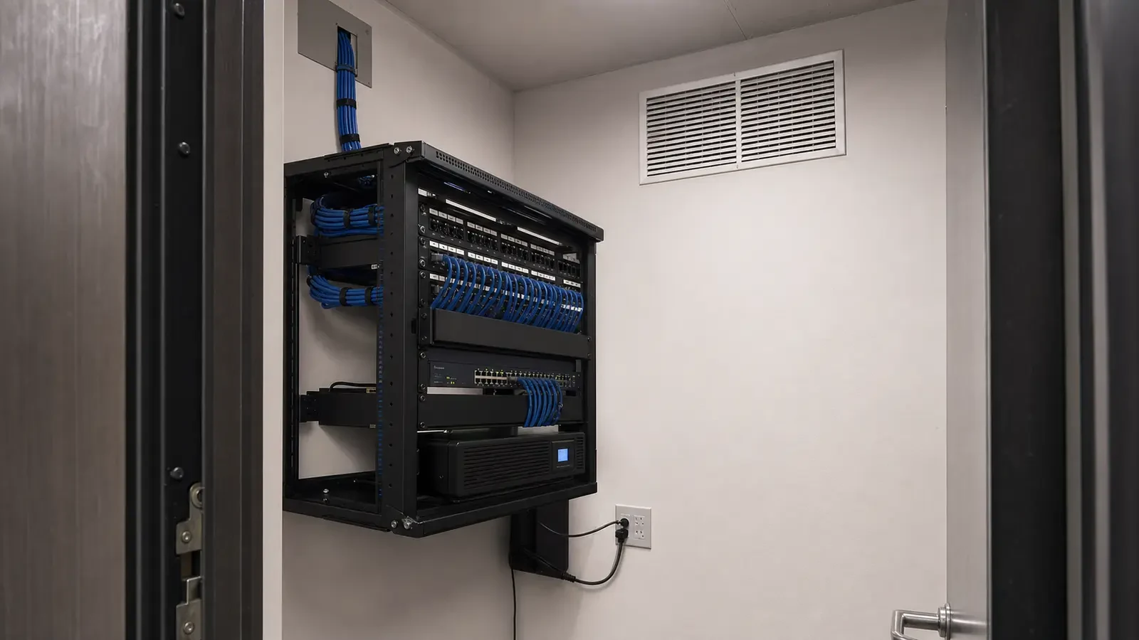
Dust, heat, cable entry, protection from operations, grounding, floor anchoring, and service access shape the enclosure plan.
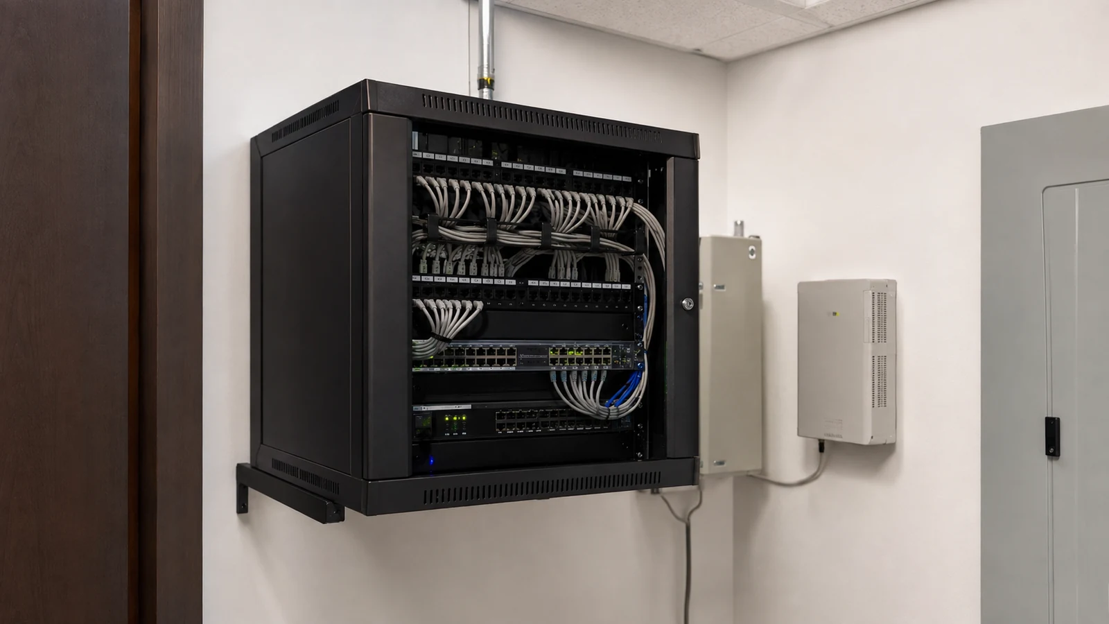
Landlord, tenant, carrier, and IT equipment need clear rack boundaries, labels, power responsibility, and restricted access.
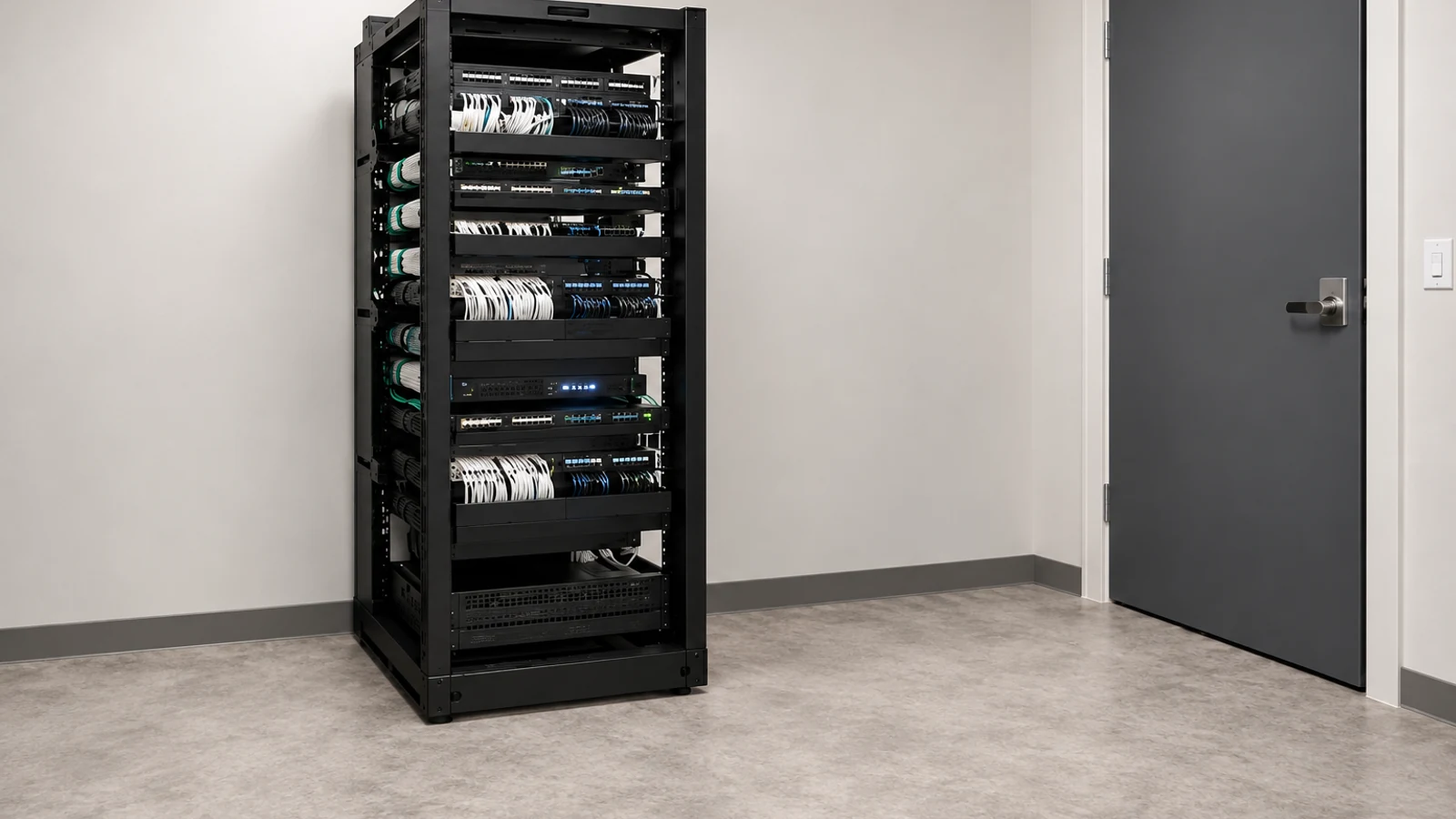
Document current ports and dependencies before moving patch cords, replacing switches, or changing power to avoid unplanned outages.
PROJECT DETAILS
Operational Recommendations
Place patch panels, managers, switches, shelves, UPS or PDU equipment, and growth space before installation.
Use actual endpoint loads and switch specifications to plan power, UPS, and ventilation.
Confirm doors, swing, wall or floor access, cable entry, and equipment-removal paths.
Align outlet, cable, patch-panel, switch-port, device, circuit, and rack-elevation records.
PROJECT DETAILS
This article helps commercial teams understand network rack installation as a technical and operational decision. It provides a common vocabulary for comparing alternatives before a property-specific design is approved.
A larger rack does not solve inadequate room power, cooling, grounding, pathway, or network design.
UPS runtime depends on actual load, battery condition, topology, and shutdown expectations; a nameplate capacity is not a guaranteed runtime.
Ventilation needs vary with equipment heat and room conditions, so generic open-space assumptions may be unsafe or unreliable.
PROJECT DETAILS
Doors, patch cords, power plugs, rails, or deep equipment may not fit or remain serviceable.
The next switch, patch panel, UPS, or fiber enclosure forces a disruptive rebuild.
Long crossed cords block labels, airflow, ports, and equipment replacement.
Switches and PoE loads exceed available power, runtime, or safe PDU arrangement.
Cable bundles, doors, walls, or shelves obstruct cooling and routine maintenance.
TECHNICAL PLANNING
Verify wall or floor support, access control, moisture, dust, heat, lighting, and safe service space.
Document rack units, rail depth, equipment dimensions, weight, doors, shelves, managers, and reserved space.
Coordinate circuits, receptacles, load, runtime expectations, PDU layout, grounding, and responsible electrical work.
Plan copper and fiber entry, patch-panel order, managers, bend control, service loops, and separation from power.
Deliver rack elevation, cable and port schedules, switch roles, circuits, UPS details, exceptions, and support ownership.
PROJECT DETAILS
RELATED SERVICES

Network Infrastructure is the primary implementation path when the article findings require a property-specific scope for rack size, depth, and equipment fit and patch-panel and switch layout.
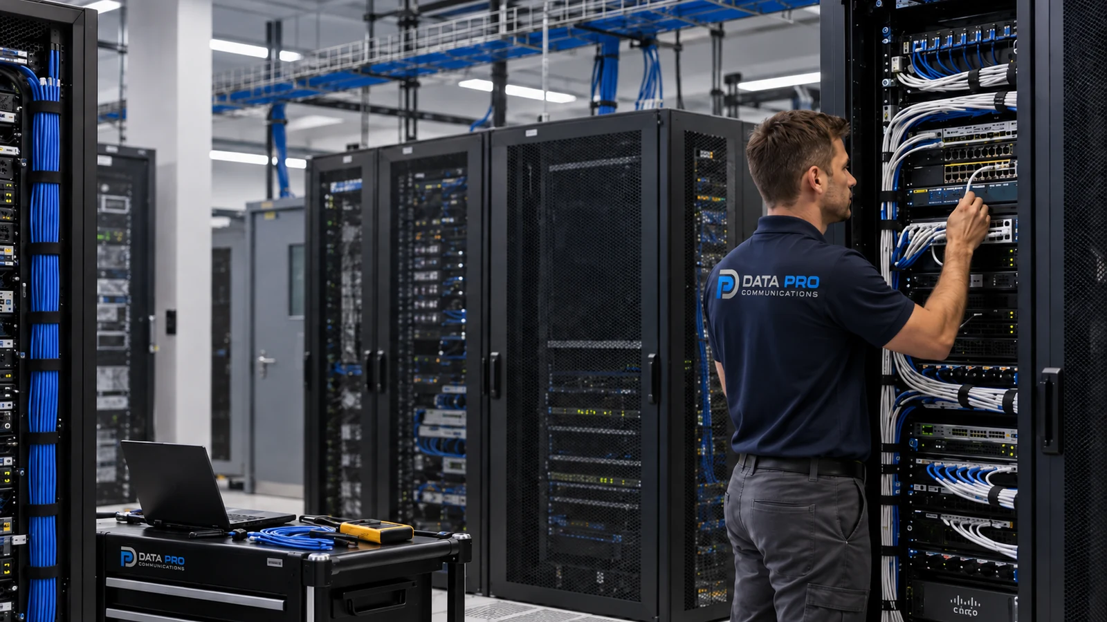
Structured Cabling supports the pathways, labels, and tested physical links involved in room and mounting suitability and rack elevation and depth.
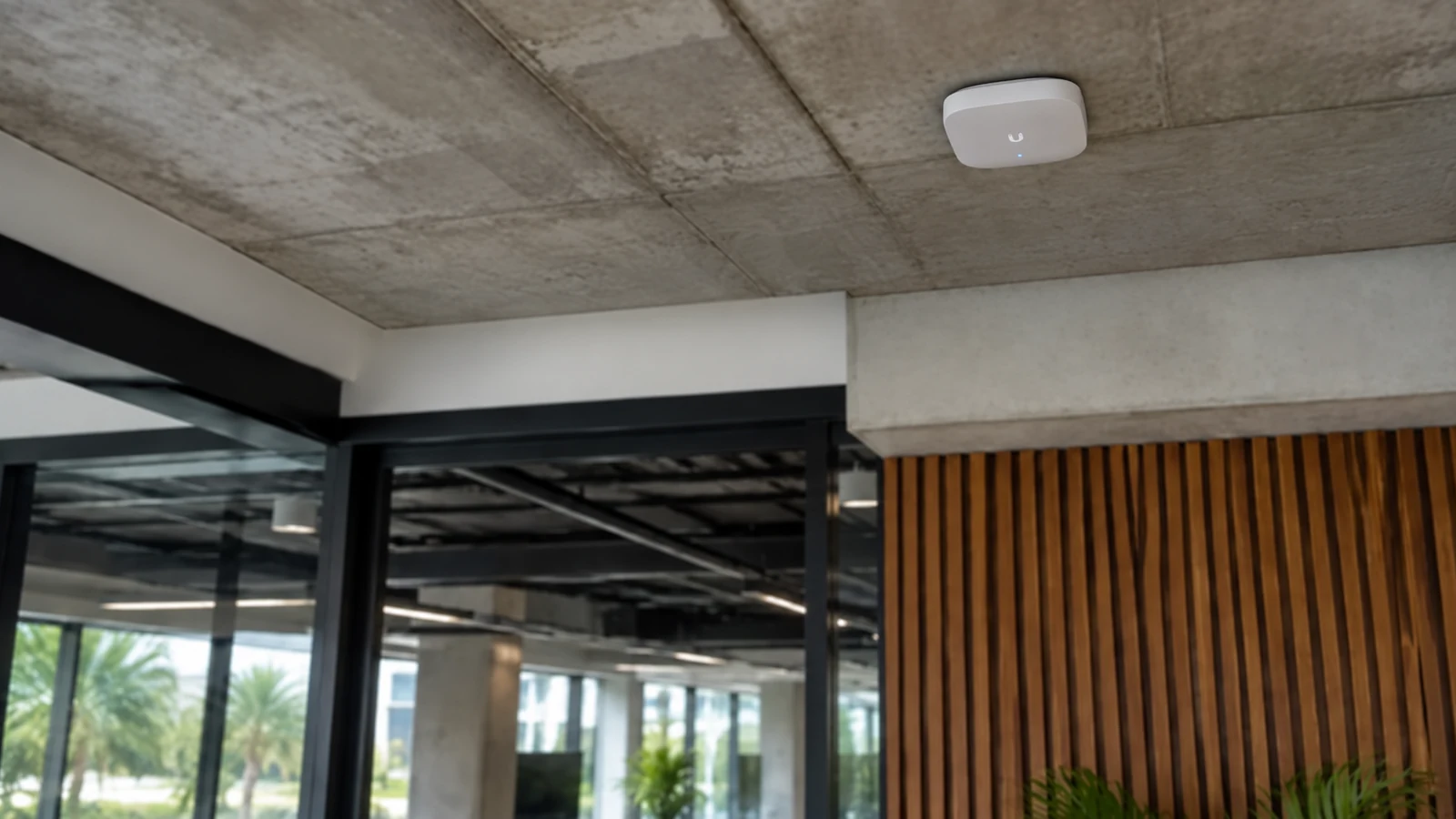
Network Infrastructure
Network Infrastructure is the primary implementation path when the article findings require a property-specific scope for rack size, depth, and equipment fit and patch-panel and switch layout.
Camera System Upgrades applies when existing equipment must be evaluated against the new requirements for rack size, depth, and equipment fit and the stated limitations.
Camera Troubleshooting & Repair uses the documented tests and dependencies in this guide to isolate faults involving labels and operating records or existing system behavior.
PROJECT PROCESS
Identify the article question, intended users, operating scenario, and the decision the property needs to make about network rack installation.
Inspect the relevant scenes and dependencies, including room and mounting suitability, rack elevation and depth, and power, ups, and pdu.
Compare alternatives against the six topic-specific concepts, document limitations, and assign implementation and network responsibilities.
Perform the acceptance checks described in the scope and deliver settings, labels, test results, exceptions, authorized ownership, and service information.
FAQ
A network rack is an operating workspace for patching, switching, power, and service, not just a metal frame. Correct planning covers rack units, usable depth, equipment weight, patch-panel order, PoE load, UPS and PDU needs, heat, grounding, cable management, clearances, labels, and expansion.
Count rack units but also verify usable depth, rail type, door clearance, cable bend space, equipment weight, and the dimensions of switches, UPS units, patch panels, shelves, and future equipment.
Group patching logically and keep patch-cord paths short and traceable. Layout should support moves and changes without blocking ports, fans, or equipment removal.
Camera, wireless, phone, and access-device loads affect switch count, power budget, heat, uplinks, and UPS runtime. Port count alone is not a complete switch plan.
Define input power, branch-circuit responsibility, receptacles, PDU arrangement, shutdown behavior, expected runtime, and equipment that should or should not be backed up.
Equipment heat, room ventilation, grounding and bonding, front and rear access, and safe service clearance depend on the actual room and installed load.
Vertical and horizontal managers, pathway entry, service loops, rack elevations, device names, port labels, and reserved rack and switch capacity keep the rack maintainable.
The most common errors include choosing a rack too shallow and leaving no growth space. Doors, patch cords, power plugs, rails, or deep equipment may not fit or remain serviceable.
Place patch panels, managers, switches, shelves, UPS or PDU equipment, and growth space before installation. Use actual endpoint loads and switch specifications to plan power, UPS, and ventilation.
Deliver rack elevation, cable and port schedules, switch roles, circuits, UPS details, exceptions, and support ownership.
A larger rack does not solve inadequate room power, cooling, grounding, pathway, or network design. UPS runtime depends on actual load, battery condition, topology, and shutdown expectations; a nameplate capacity is not a guaranteed runtime.
Survey the rack location when equipment dimensions, wall or floor support, heat, power, grounding, cable entry, clearances, or current port dependencies are uncertain.
Survey the rack location when equipment dimensions, wall or floor support, heat, power, grounding, cable entry, clearances, or current port dependencies are uncertain. The resulting scope should state technical criteria, limitations, responsibilities, and acceptance tests before installation begins.